This section is expanding to include details of other hybrids as i find them or have time to write them up.
The Bagley polygon (rat-race) (no ballast load)
The Wilkinson (Coax) (balanced 100ohm ballast load)
The Wilkinson (lumped components) (balanced 100 ohm ballast load)
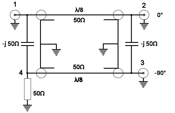
Capacitively coupled hybrid (2 port) (unbalanced 50 ohm ballast load)
3db Coupler (unbalanced 50 ohm ballast load)
The Gysel, like a 'Wilkinson' but with unbalanced 50 ohm ballast loads
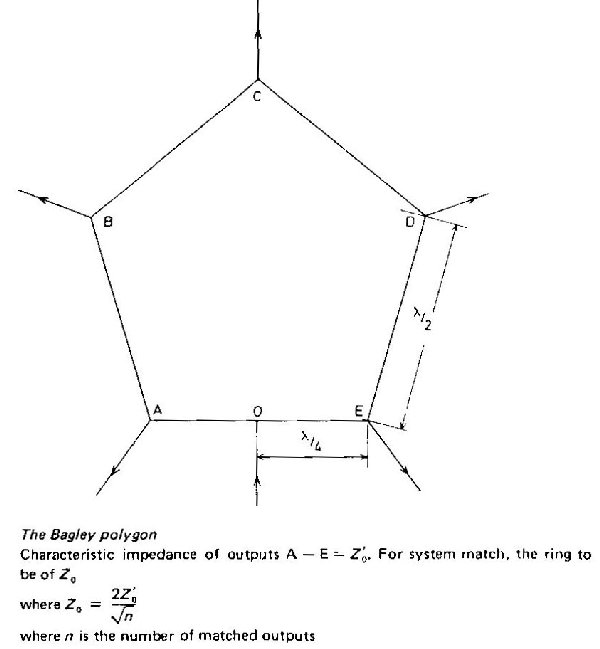
The Bagley polygon
This device can be used as a signal combiner or as a power splitter. It can be thought of as a generalised form of rat race.
A five-sided form of this circuit is shown in Fig. 18.56. Suppose that a signal is fed in at 0; this will divide into two equal parts going round the loop clockwise and counterclockwise. Using arguments analogous to those used with the discussion of the rat race, it is seen that the signals add at the points A, B, C, D and E giving equal signals at each. Thus it acts as a five-way power splitter. It will be noted that alternate points A, C and E are in antiphase to those between them at B and D. In order to bring all into phase, a length of line a half wavelength long can be added in the feeds from B and D.
If the network is fed by five signals at A, B, C, D and E each will cancel at each of the other input points but will add at 0. Hence provided that the phase of the sources at B and D have been reversed by an extra half wavelength of line, the polygon acts as a five-way signal combiner.
Similar reasoning can be applied to any polygon with an uneven number of sides. If it is desired to combine an even number of signals, or to split power into an uneven number of parts, this can be done by using a polygon of one more side than the number of parts and then omitting a connection from one of the junctions, preferably the one opposite to 0.
The matching of the polygon is achieved when the characteristic impedance of the quarter-wave lines OA and OF is
|
Zo= |
where Z0 =characteristic impedance of the lines connected at A, B, C, D and E and n = number of loaded junctions.
It is usual to make the half wavelength long sides of the same characteristic impedance as the quarter-wave line, as this minimises the VSWR on the sides of the polygon.
This circuit can be made of stripline for microwave use. It has the advantage over other forms of power splitter (or signal combiner) that it does not call for a wide range of characteristic impedances in order to match. This is because the polygon Z0 is proportional to square root 'n' for impedance matching. Thus if Z0' is taken as 50 Ohms the values of Z0 for matching, for various values of n, are as shown below:
| N= |
3 |
4 |
5 |
7 |
9 |
11 |
Zo= |
57.7 |
50.0 |
44.7 |
37.8 |
33.3 |
30.2 |
It will be seen that in each of the above cases the Z0 of the polygon will not differ much from 50 Ohms and, when made of stripline, require strip widths differing little from that used for 50 Ohms.
----------------------------------------------------------------------------------------
Described in Radcom Sept '88 as part of an article by G3WZT on high power solid state amplifiers. This has been generalised for use at other frequencies. The capacitor is shown a -j50ohms ie 50ohms capacitive reactance at the operating freq. For example c= 22pf at 145MHz, 45pf at 70.2Mz, 63pf at 50.5 MHz The 1/8 wave lines must take into account the velocity factor of the cable.. you could cut a 1/4 wave as described in the harmonic suppression of this site and then chop it in half (I suggest cutting it for a slightly lower frequency, which will make it a little too long and thus allow for terminating the cut ends).
Back to the Technical info index
