Simple Low Pass filter for 50 MHz
Parts List
Simple Low Pass filter for 50 MHz
Parts List
L1, L3 ..6 Turns 1mm dia Cu wire 1.25 cm long nominal,
L2 ...6 Turns 1.2mm dia Cu wire 1.25 cm long nominal,
C1, C4 .47pF Mica 350V working
C2, C3 .100pF Mica 350V working
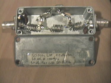
The Inductors are supported on the RF sockets and on ceramic pillars. Adjustment for best VSWR 'in band' when terminated in 50 ohms is achieved by squeezing or compressing the coils slightly, (and symmetrically so that L1 and L3 look the same).
Through loss in band on my unit is 0.2dB, with 30dB return loss (better than 1.1 :1 VSWR)
For info, a conversion table of Return Loss to VSWR is on this site. Beats the hell out of doing the sums!
Attenuation at 100 MHz and above is at least 30dB. The unit handles
300W without problems, and has been tested short term to 500W.
Additional Filtering to remove the second harmonic is applied directly to the output of the Amplifier, and consists of a coaxial 'T' piece with a short circuit 1/4l (at 50 MHz) stub.
This becomes 1/2l at 100MHz and shorts out the second harmonic (and 4th and 6th etc where it is a multiple of 1/2l )
To cut the cable, find a strong steady incoming signal at about 50 MHz and put on the 1/4l (at 50 MHz) stub. This should be left OPEN cct and cut for a minimum signal from the 50 MHz source. The inner and outer can then be cut back just enough to allow some copper tape to be soldered from inner to outer to form an effective short cct.
This technique can be applied to almost any amplifier
on any (VHF or UHF) band, and is very low loss and has very high power
handling (dependant on the coax and connectors used)
