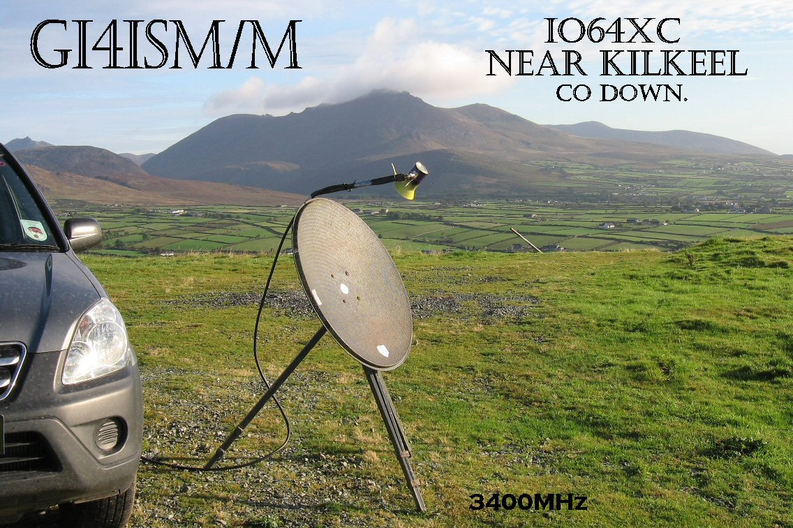
9cm (3400MHz)
Link to EME activity
Link to info on surplus Ionica equipment
GM4ISM home and Portable 9cm equipment
Equipment for 9cm is an old DEM single board transverter retuned from 3456MHz to 3400MHz.
Power is raised to 600mW in a further 3 stages, Preamp using FHX05 is under construction.
Portable equipment and operation
My portable station now (March 05) comprises the DEM single board transverter + integral 600mW PA, and a PA / preamp system built around Ionica bits.
The Ionica PA (unmodified) gives 15W, I have cut the front end stages from an RX block for a preamp, and chopped one of the pin diode attenuator sections from the base station motherboard to give me a 10-30dB variable attenuator for the power amp input. The whole lot runs from 12V, as the -12V is generated by an inverter (see the PA mod page), and this also allows the use of a 28V coax relay. as a simple indicator of TX op power I have used the inbuilt RF detector output to drive a LED via 270Ohm resistor. Brightness varies with output power.
QSOs G3XDY at 470km via aircraft scatter from a portable location near Gatehouse of Fleet, Dumfries and Galloway,
G3UKV first GI to G @279 Km (Tropo) GM4LBV first GI to GM (tropo) G3XDY at 535km via aircraft, scatter from a portable location near Kilkeel Co. Down
The antenna was an 80cm sat TV dish with a simple flared tin-can feed.

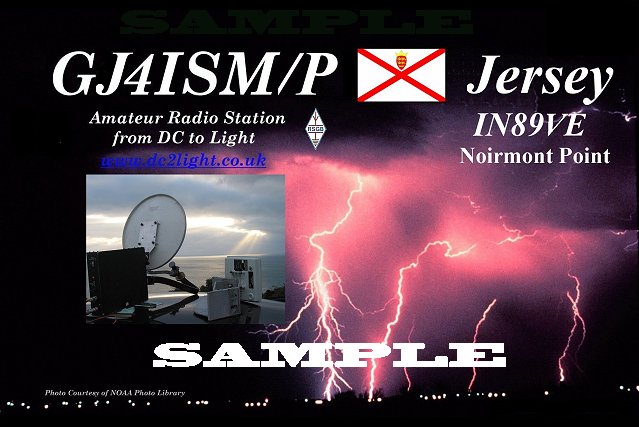
mini DXpedition to Jersey 11-13th October from IN89WG 2 QSOs on 9cm, G4ALY first GJ to G and G3XDY (390km)
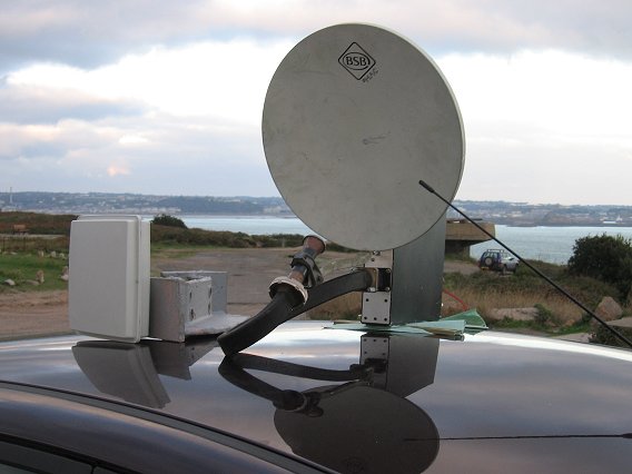
using the same equipment but with a 6" square patch antenna from Airspan equipment shown below with the 3cm transverter and dish, overlooking St Hellier
I had planned to use 3 of the Ionica PA units combined to give about 50W for home (EME) use, though I have now obtained a single Toshiba power amp (Thanks to John GM4LBV) that will do that job without the hassle of a power combiner.
Full circuit diagrams of the PA and some parts of the motherboard can be downloaded here . Zipped up they total about 6Mb They are password protected, as I have been asked to ensure that they are not available for commercial use. Email me to request the password.
Ionica Base Station Power amplifier.
These are 4 stage, using 'normal' FETs for the first 3 stages, and an internally matched device as the final stage.They work on the amateur bands 3400 MHz to 3456 MHz without modification. Less than 1mW drive is required for about 15W output.
PA output device is a TIM3742 -16 nominal 18W out (42.5dBm) 3.6 GHz to 4.2GHz. Other Units use the MGFC42V3436 Spec'd at 42.5dBm 3.4 to 3.6GHz and a HP device (no data) Ionica PA circuit boards are identical for all units seen to date.
In Feb 01 I had 20W saturated op on 3400 MHz from one of the Ionica amplifiers (modified). I had to manualy bias each device, but no other modification was required. The amplifiers have been used on the 3456 MHz sement of the band without problems
Unmodified, using the on board bias control, the devices are run in a constant current mode designed for class A operation. Only 4A is allowed into the final device, limiting the op power in an unmodified state to about 14W.. but less than 0dBm drive! The beacon near Dundee ran for almost a year continuously with an unmodified Ionica amplifier. It was switched off due to RF hazard concerns, but has been re-located at GM4LBV's QTH on the coast near Montrose
See the PA Use & Modifications page
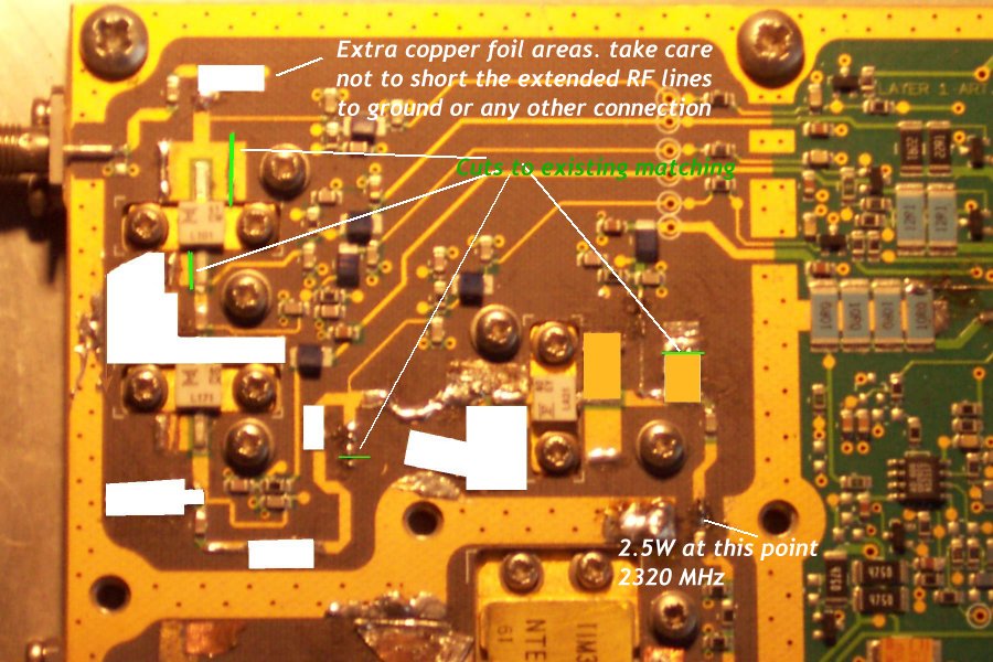
Some detail of the experenental matching changes to the first 3 stages to allow operation on 2.3GHz.. I have got 2.5W out for 1mW drive, the PA device has proved difficult, as there is very little room to put tuning tabs on the board. These are for guidance only, you may have to tweak the matching to acheive the same results.
I have also done some work on the receive converter which is found in the Ionica base station mast head units. This can be modified quite easily for use on the amateur bands with very reasonable performance.
See the Receive converter page
Adam G0ORY has been doing things with Ionica Consumer units (mainly on 13cm) and now base stations, and is working on a webpage
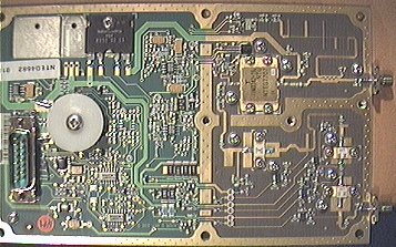
PA block ( 1 of 3 to be combined for EME)
Large image 308 Kb
More of the Ionica base station gear is here (some are thumbnails, click to see larger image)
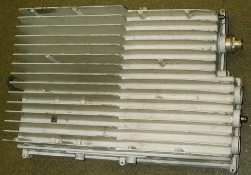
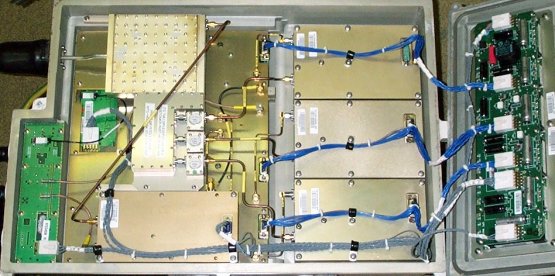
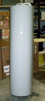
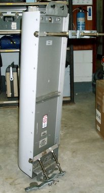
Ionica antennas (Horizontal poln Version)
 |
 |
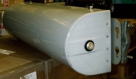 |
| some of these antennas are in use at GB3MHX |
|
Pictured below is a poersonal 9cm Beacon and its antenna at GM4LBV's QTH a few yeas ago Call was formally GM4ISM/B QRT in June 02 due to RF hazard concerns Antenna 120 ETN 120 Deg Beamwidth 14dBi With a little work if could be updated and put back into use if anyone has a good place to put it on! . |
||
|
3.4 GHz Beacon antenna in IO86RQ
|
Beacon transmitter, 3400.054, 14W op
|
|
3400 MHz EME
Pictures below!
May 2008 work started on EME system
progress as of 24/5/08 Septum feed (with flare suitable for my dish with 4.5 f/D) completed
Measured parameters for the feed in iosolation. RX return loss @ 3400 MHz 32dB, TX return loss 28dB
Cross Polar isolation 29dB
Update Friday 6 June. Power amp has been soaktested on the bench. steady 42W available.
All that remains is to attach the PA to the dish, wire up the ptt system and operate....
Update from the activity weekend 7th and 8th June 2008
On Saturday, some minor bugs and family commitments caused a late start, but
once I had the dish pointed at the moon, I was pleased to see a little moon
noise. (about 0.1dB now I have measured it as best I can) This was just enough
to aide tracking, though very easy to miss. My tracking system has no
feedback into the shack.. effectively I have AZ and El control, optical tracking
when it is clear, and a practiced knowledge of the speed of the
actuators, such that I was able to stay on the moon most of the time. Room for
improvement though it must be said, a lot of effort went into keeping on
the moon.. I could make it easier for myself HI
Heard on Saturday were OK1CA at M , G3LTF at T copy, W5LUA O- M other signals
heard not identified. signals definitely degraded as the evening progressed.
VE6TA was detectable only on Winrad, far to weak to read any CW, though I suspect
QRSS would have been viable, the trace was clearly visible and
reasonably constant. No QSOs resulted on Saturday, though several people reported
some marginal copy of my signals.
Sunday, a minor tweak to the preamp gained a little lower noise
figure, but not much. Sun noise now 7.2dB
Conditions seemed better though, and I completed with G3LTF fairly easily..
not strong, but good M copy. (the only QSO that is not a country First HI)
OK1KIR was good copy O much of the time, but was struggling to hear me.. a couple
of periods he sent almost nothing but M report, and I responded in
kind with my RO report . Finally I got rogers.. Hard going but worth the effort.
This is probably a first GM to OK on 9cm
A test with Al W5LUA resulted in a lot of T reports clearly heard.. not very
encouraging, then suddenly Al was able to hear me better and the QSO
completed.. #3 in the bag. A good report from F2TU was obtained later, and finally
a very easy QSO with Willi LX1DB OO. RST reports exchanged Willi was 539, and
I got 449 back.
From these contacts I seem to be hearing about the same level
as I am being heard. This ties in with the performance of my preamp which is
as far as I can tell about 0.5dB nf
It is obvious though that the dish is not delivering the expected gain, and
thus I will need to do some work on the feed.
After removing the flare, the illumination of the dish is more uniform, though overspill seem to be degrading the noise performance. Overall on receive I have not seen an improvement, but I may be louder.
Recently I have worked RW1AW on random about 1 hour befor an arranged sked (a very fine signal, Alex came staright back when I answered his CQ, 529 539 exchanged)
A first GM to Russia on 9cm too HI... Initial #5
Worked LX1DB again a few days after Alex, though with the moon low in the sky and nearer apogee and near the sun the signals were not so good.
![]()
Page under construction
Back to the Amateur Radio page
New counter from 3rd October