Use and modification of Ionica Power amps
Use on the 9cm (3400MHz) Band

To make these ex Ionica amps work on 3400 MHz -3456 MHz no retuning is required. At the time of writing, least 3 beacons in the UK were active using Ionica amps 24/7
Pin-out of the 15way D type connector.
| 1 | RF Detector OP. Approx 6.5V at full op. High Z | |
| 2 | Some info says Ground.. On mine it is not! leave O/C Bias??? | |
| 3 | Reset Error output (also used to enable original PSU) | |
| 4 | Mute (+5V to transmit) | |
| 5 | -12V @ approx 75mA | |
| 6 | 0V | |
| 7 | +10V @ approx 5.7A (unmodified bias) | |
| 8 | +10V NB Use all +10V Pins for current sharing | |
| 9 | RF Detector ground | |
| 10 | Temperature OP | |
| 11 | Error OP | |
| 12 | +12V @ approx 25mA | |
| 13 | 0V | |
| 14 | 0V | |
| 15 | +10V |
 |
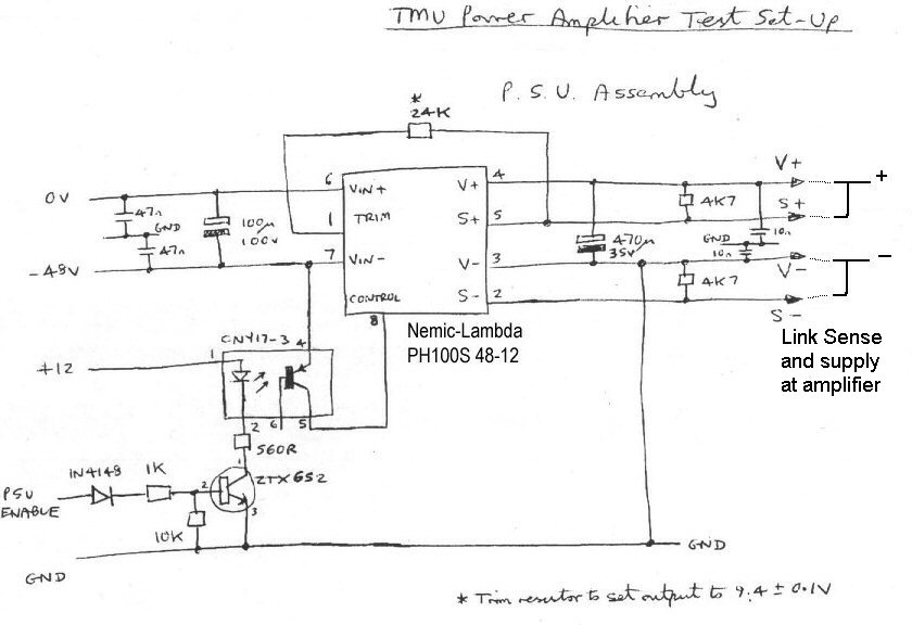
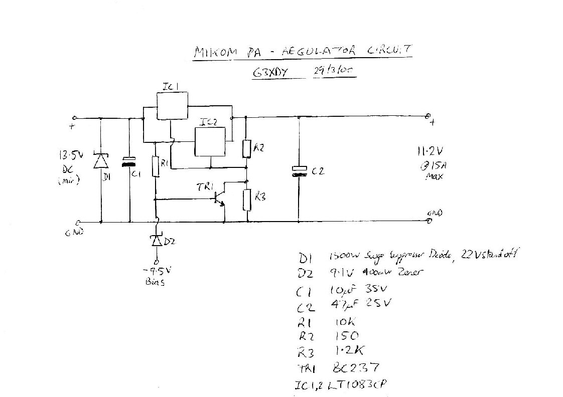
Ionica Test Setup Circuit from handwritten notes. (not mine!) The use of the Reset error seems to be unnecessary for most applications.
|
 |
Ionica Test Setup Circuit from handwritten notes.(not mine!) Not verified or tested to date. |
|
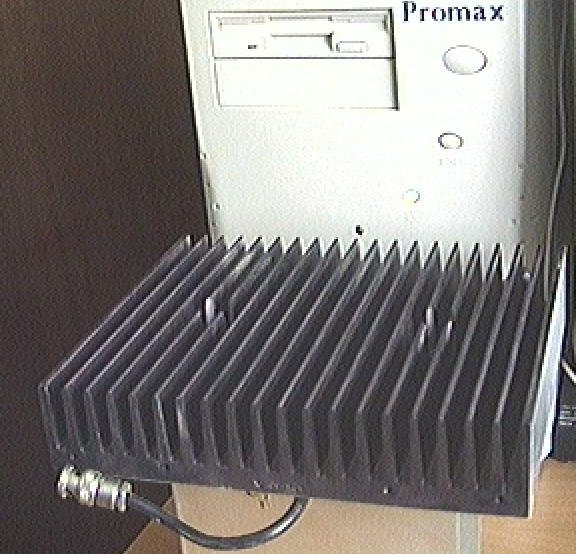
Heatsink used on test. No forced airflow. A similar heatsink is installed on my /P amp. see the 9cm page |
Note sense and supply must be linked at remote end. The 4K7s prevent overvoltage if sense link is disconnected. |
I have not checked out all the above info yet .. Many of the diagrams and test setups are from a third party and refer to the full Ionica amplifier system with original Nemic Lambda power supplies.
The onboard bias circuits is activated by using the above circuitry. The circuit is constantly trying to keep the RF transistor currents constant! The output power is limited by this to about 14W, a little more if the input voltage is raised to 10.4V, which applies the device maximum of 10V to the PA. Bare minimum, apply -12V, +10V, +12v and a logic 1 to pin 4 and the amp will run. No modification is required at all if 14W is enough! Drive level will be between -7dBm and -2 dBm typically. The extra power is barely worth the effort of doing any modification.
I have had one Ionica amplifier loose logic functionality when the +12V rail exceeded 13.7V.. An internal voltage reference chip gave an abnormal output. Ensure that the voltage applied to pin 20 cannot exceed about 12.5V for reliable operation.
To get the full potential of the Ionica power amplifier (about 18W at the 1 dB point), it is necessary to modify the bias ccts to the form in which I did the initial testing (or similar.. not constant current but constant voltage at low impedance). The mute cct and +12V line are not required with the simple modification described below. A more sophisticated approach will be to use the on board current sensor, and fool it into beleiving that the device is passing a constant current. The mute cct would then be enabled.
I have run the modified Ionica unit (bias fixed) at 10.0V, which brings the devices up closer to their max operating voltage. With 5mW drive, @ 3400MHz, 20W CW op was obtained. The amp was nearly saturated at this level, 1dB compression point was about 18W. I ran the amp for 20 minutes key down, and with the heatsink above, I was able to hold my finger on the PA device without discomfort. Output power had dropped 0.1 dB after about 5 minutes, and remained stable after that.
Arie, PA0EZ reported that his Ionica amplifier would oscillate if the input was left unterminated. I have never run up the amps without an attenuator on the input, as I have too much drive.
My portable setup uses one Ionica amplifier, running from 12V. John G3XDY sent me this cct, which he used for a 10GHz PA. Only one LT1083 regulator is required for the Ionica PA, if unmodified. The regulator must be well heatsinked. The cct provides a certain amount of protection from loss of the -Ve bias supply, shutting the regulator down to its minimum voltsge of 1.25V. Note an 11V Zener was used for D2 in my version with a -13V rail.
See the 9cm page for pictures.
John G4BAO has sucessfully combined 2 of the Ionica amplifiers using cut down parts from the original amplifier combiner / filter.
See his project here
Details of the Nemic lambda DC-DC
converters here. Note
that the sense and voltage lines should be connected with wire. The
pull up resistors shown in the diagram are probably to ensure the
supply goes low when disconnected.
Full circuit diagrams of the Ionica PA and some parts of the base station MHU motherboard can be downloaded here. Zipped up they total about 6Mb. They are password protected, as I have been asked to ensure that they are not available for commercial use. Email me to request the password.
Whatever you do, make sure the +10V is never applied without the -12V present ! The full implementation of interlocks as designed with the nemic Lambda modules will protect the amp. Note that without the +12V rail, the bias control does not operate.
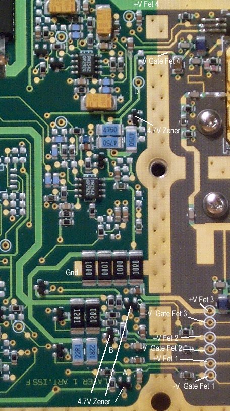 |
Modified Bias cct as originally tested Shown to the left is a close up of the part of the Ionica PA where the RF section and DC section interface. All the supply lines are identified, along with the bias points A,B,C,D & Gnd at which I applied the 'variable Zener' circuit to set the bias for each device. This cct is applied in parallel with the existing 4.7V Zener.
Diode is 1N4148 or similar, 5K pot, and a BCY72 or almost any small PNP transistor . I am building a small bais board, which will be placed above the main board. There are undoubtedly more sophisticated bias circuits, but this seems to have a low enough impedance to set the standing current with good stability. The cct diagram gives values of standing current for the FETs thus
|
Data sheets available for the first 2 devices from Fujitsu in Adobe Acrobat format FLL101ME and FL171ME , The Toshiba Fet TIM3742 -16 (no longer on maunfacturers site)
and the MGFC42V3436 (no longer downloadable from the manufacturer's website.)
Adobe PDF reader is required to view these.
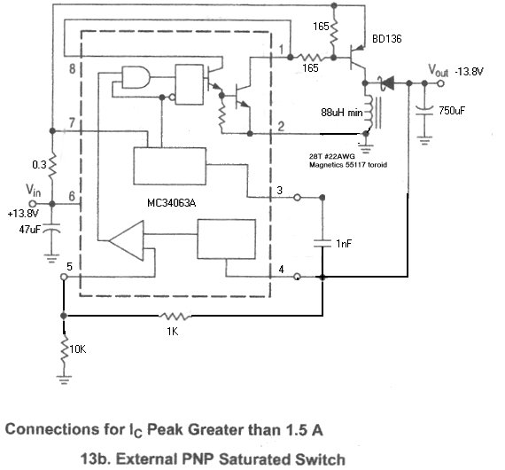
-V bias supply used on my portable system.This runs for +12V DC and produces -13.8V out
I used a surplus dropdown regulator and the components my not be optimal, especially the inductor. Slightly better performance may be possible by selecting component values as per MC43063A data sheet. The circuit described here is capable of 500mA (drops to 11V at 500mA) and is more than adequate to work with the +ve rail to run the 28V relay.
New counter from 3rd October
