122GHz (2.4mm wavelength)
VK3CV 122GHz
Equipment for 122GHz is a VK3CV 'transverter', still to be boxed up.
Classic diode multipliers are also under construction to provide test sources.
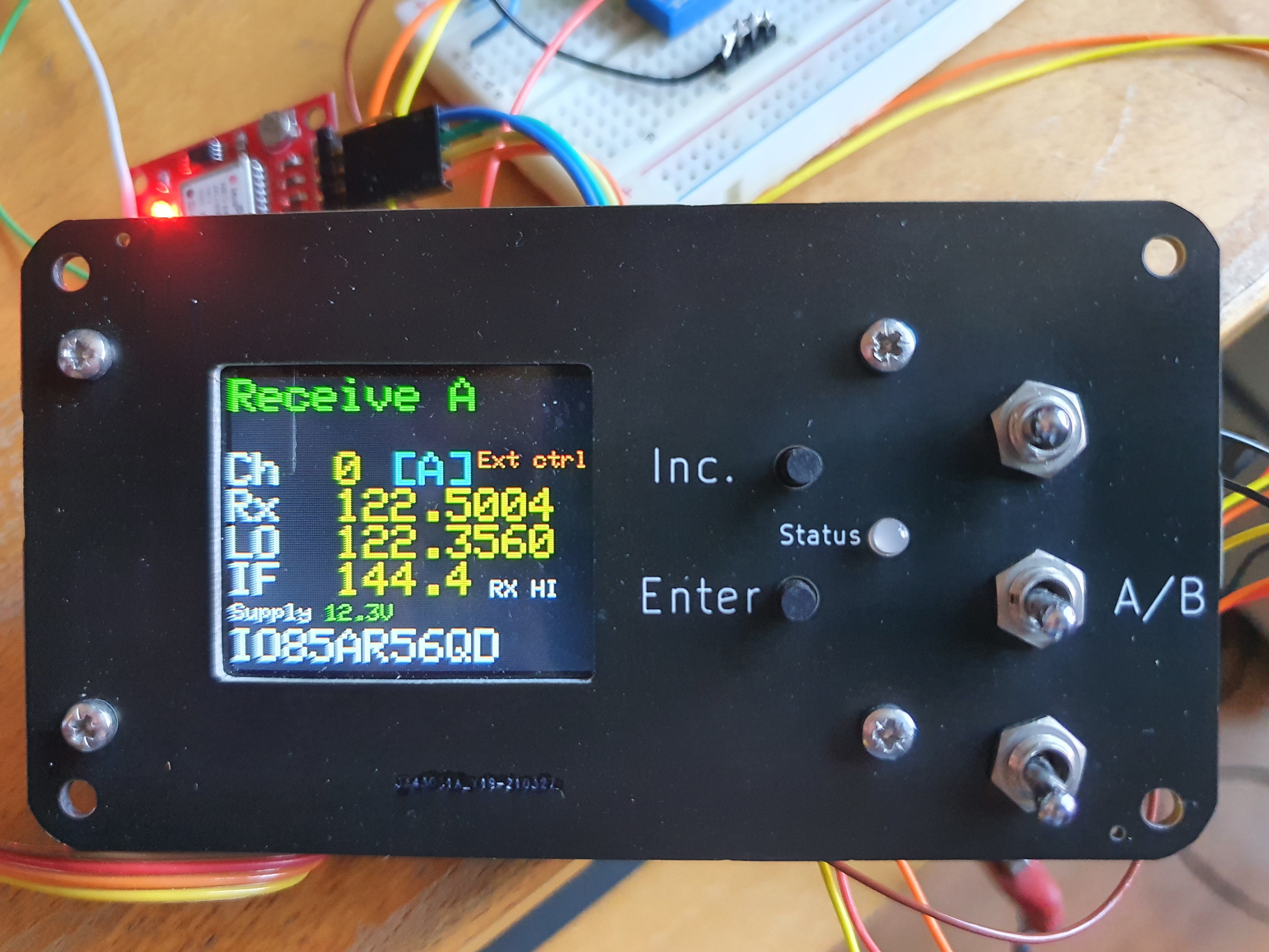
As part of my system, I decided to implement Barry, G8AGN's Arduino TFT display design.
This provides a good visual indication of the operating mode as set by the various switches.
His original design and Sketch can be found on the 122GHz reflector.
It should be noted that if the VK3CV unit is powered and the arduino is not, then the pins on the arduino are no longer very high impedance (internal protection diodes)
This is likley to effectively ground the switch inputs and the channel / mode selected will not be as expected.
This is not expected to cause any damage but is not a reccomended condition and I havent tested it.
VK3CV Transceiver support display project
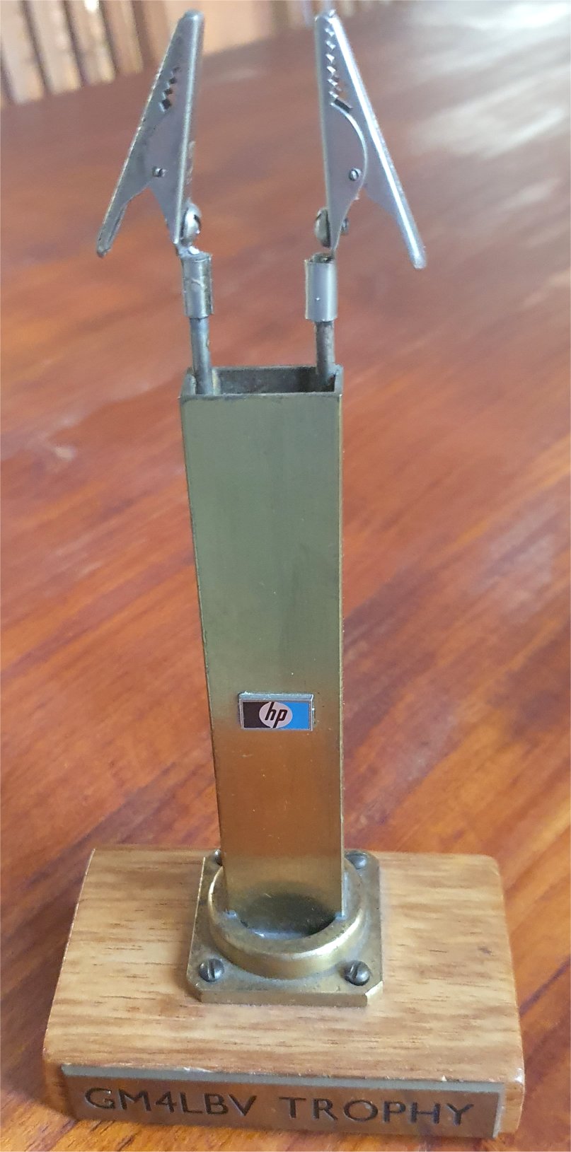
Winner of the Scottish Microwave Round Table (GMRT) construction contest 2022.
The infamous 'Wave-guide to crocodile clip adaptor'
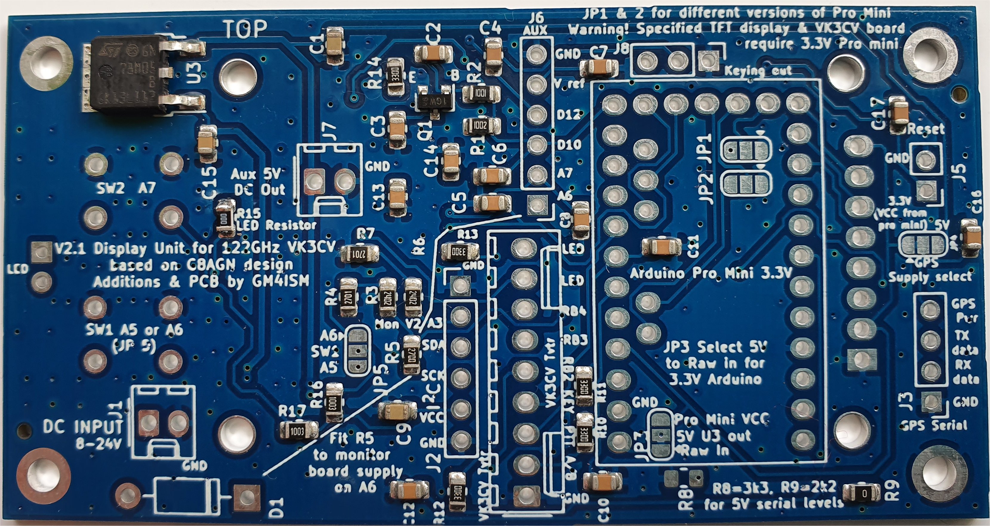
I decided to design a PCB to make wiring easier and also decided that I would try to make the display capable of more functions.
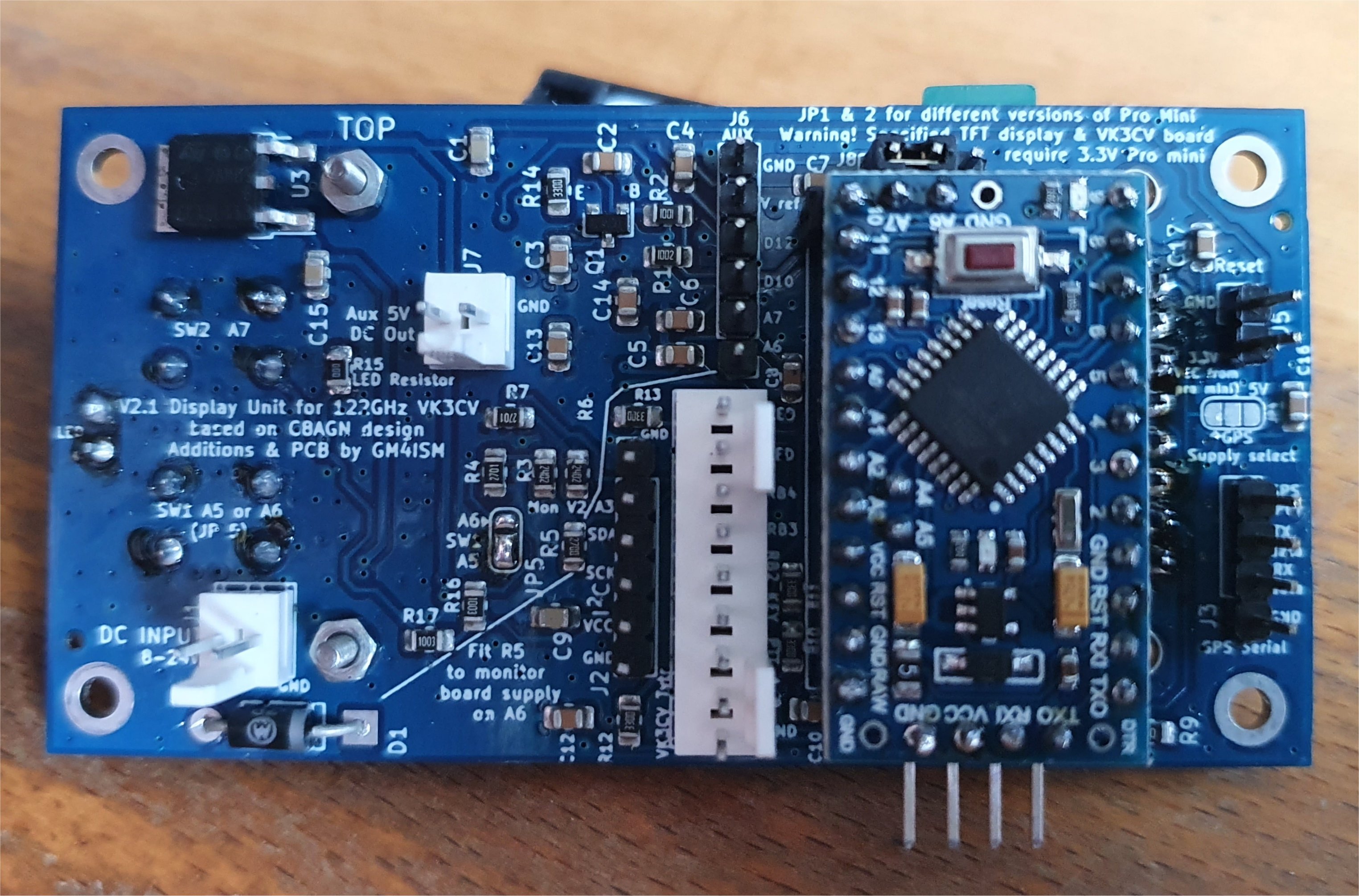
The result is seen below. It has become rather more complex and has been designed with as much flexibility as possible.
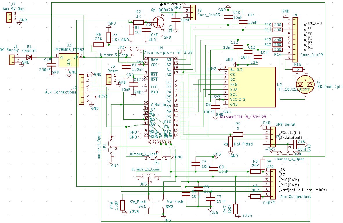
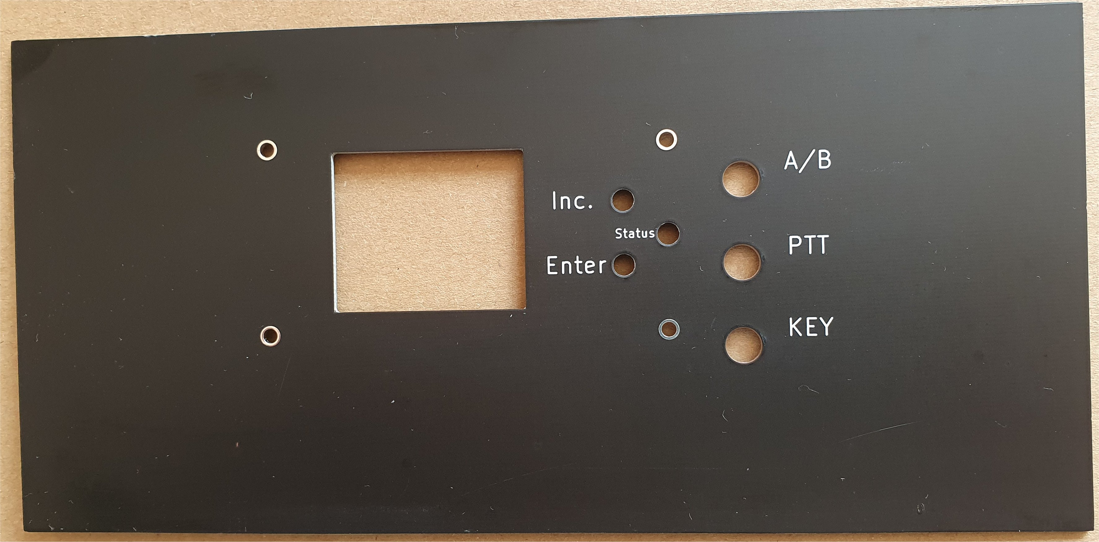
Prototype display front panel, V2.1 display board and schematic.
My implementation has several additional features :-
-An on-board 5V regulator, to reduce stress on the Arduino 3.3V regulator.
-Display of board supply voltage and can display a second DC voltage 0 to +30V.
-Buttons on the PCB allow you to set the VK3CV board channel.
-A simple 6 message programmable (no PC) CW Auto Keyer is implemented.
-Indication of whether the RX is above or below the LO and an output to control a switched Quadrature combiner.
-I have modified Barrys sketch to do all this and my version is published with his permission.
-The board is still compatible with Barrys original Arduino sketch and then doesn't need all the extra components.
-A matching front panel / display bezel, fabricated as a PCB is also available, in 2 largeish sizes that the user must cut to fit their enclosure.
The 2 sizes are
120 x 95mm marked for Hammond 1590B (a tight squeeze), Hammond 1590T, Hammond Eddystone 29830 - 26908 PSLA
200 x 95mm, marked with all the sizes of the medium board and also big enough for EAB 2.0-200W-200D (RS Components 188-1264) extruded enclosure which is 200 x 86 x 200mm deep. see also RS 188-1265, 1266.
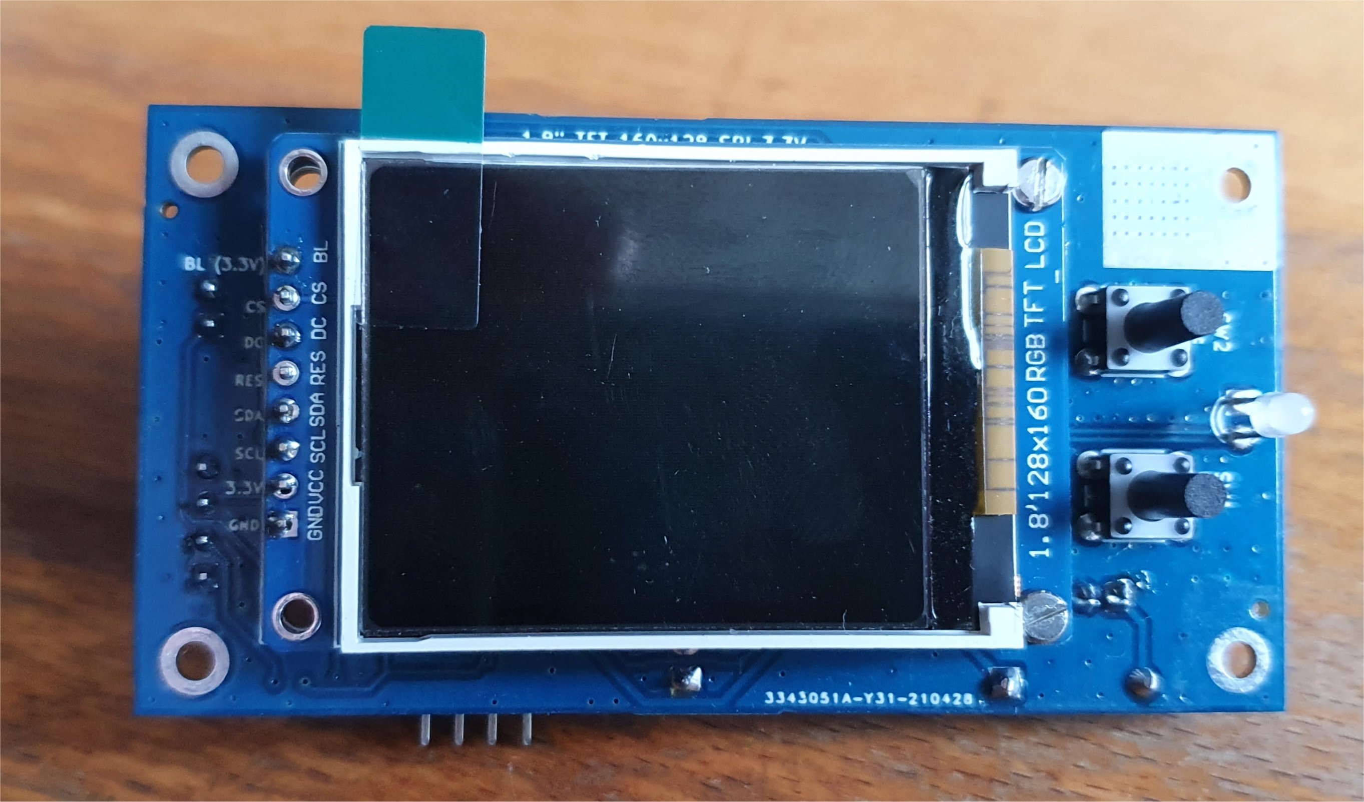
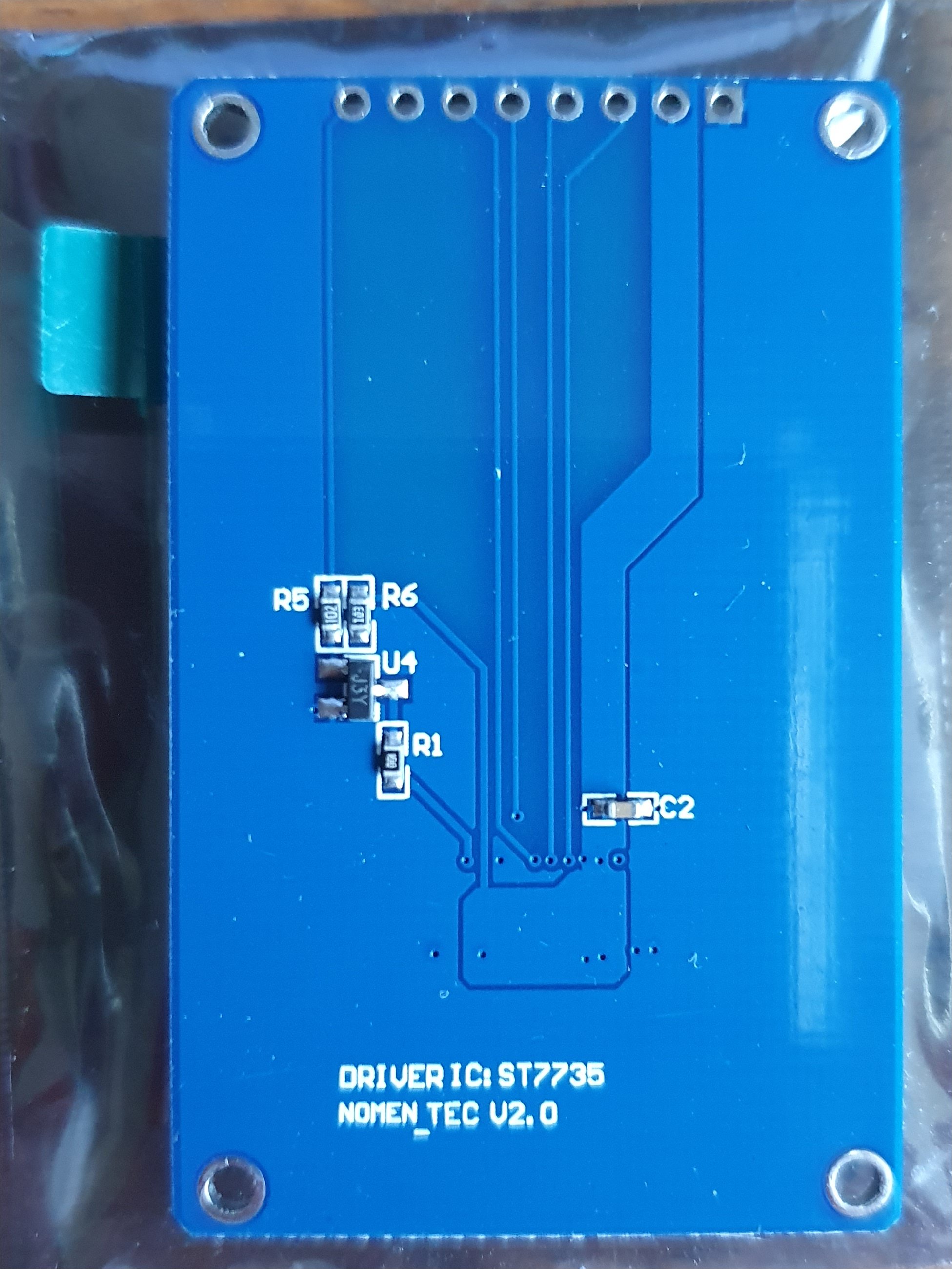
The 1.8" 160x128 3.3V TFT Display I used was from eBay seler cayin35, item No 193545945157 The item description has full details but essentially the drive IC is ST7735S
Size is 35(W)*56 (H)*3.45+/-0.1(T)mm. The rear of the TFT display says NOMEN_TEC V2.0
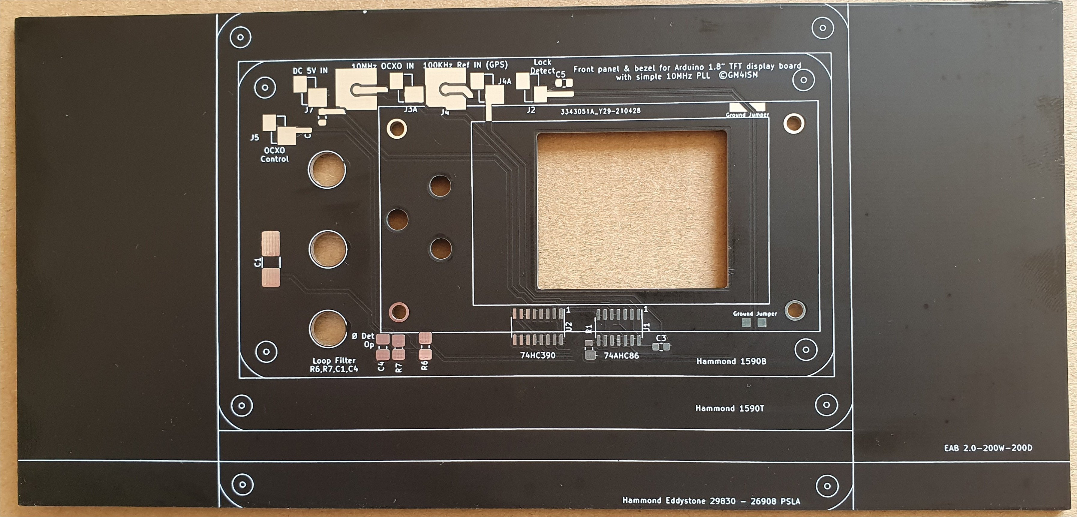
-Pictures above are the 200 x 95 mm board. Markings dimensions are from drawings of the boxes. Tolerences may vary so they should be used as guidlines only
-The optional circuit on the rear of the front panel (which fits round the mounted display board) is a simple 10MHz PLL operating with a 100KHz reference
-It is similar to a number of designs for the Jupiter GPS, NEO-6M eg G3RUH. I have only done basic tests, stability may not be ideal for 122GHz.
With a good OCXO, I found the basic design usable as a reference for 10GHz SSB / CW. The board will not be supplied populated with these components
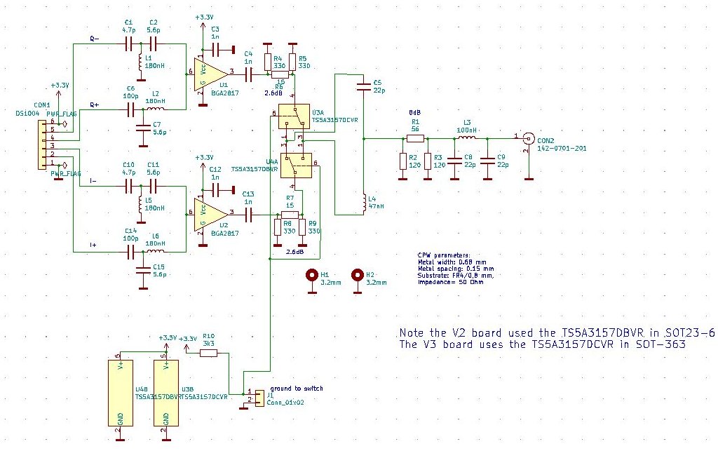
-A modified version of Pawel, SQ1GQC's Quadrature combiner, with IQ switching to allow rejection of image to be swapped from high to low is being tested.
Again modified and published original contributors permssions.
Please note the V2 board used the TS5A3157DBVR in SOT23-6 , the V3 board uses the TS5A3157DCVR in SOT-363
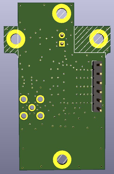
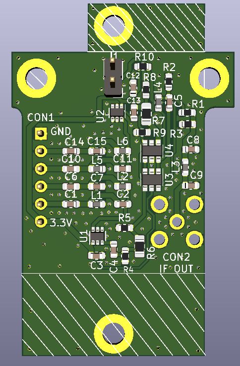
3D models of fully populated quadrature board. N.b. 'populated' PCBs I sell will in future have the MMICs fitted.( from April 2023)
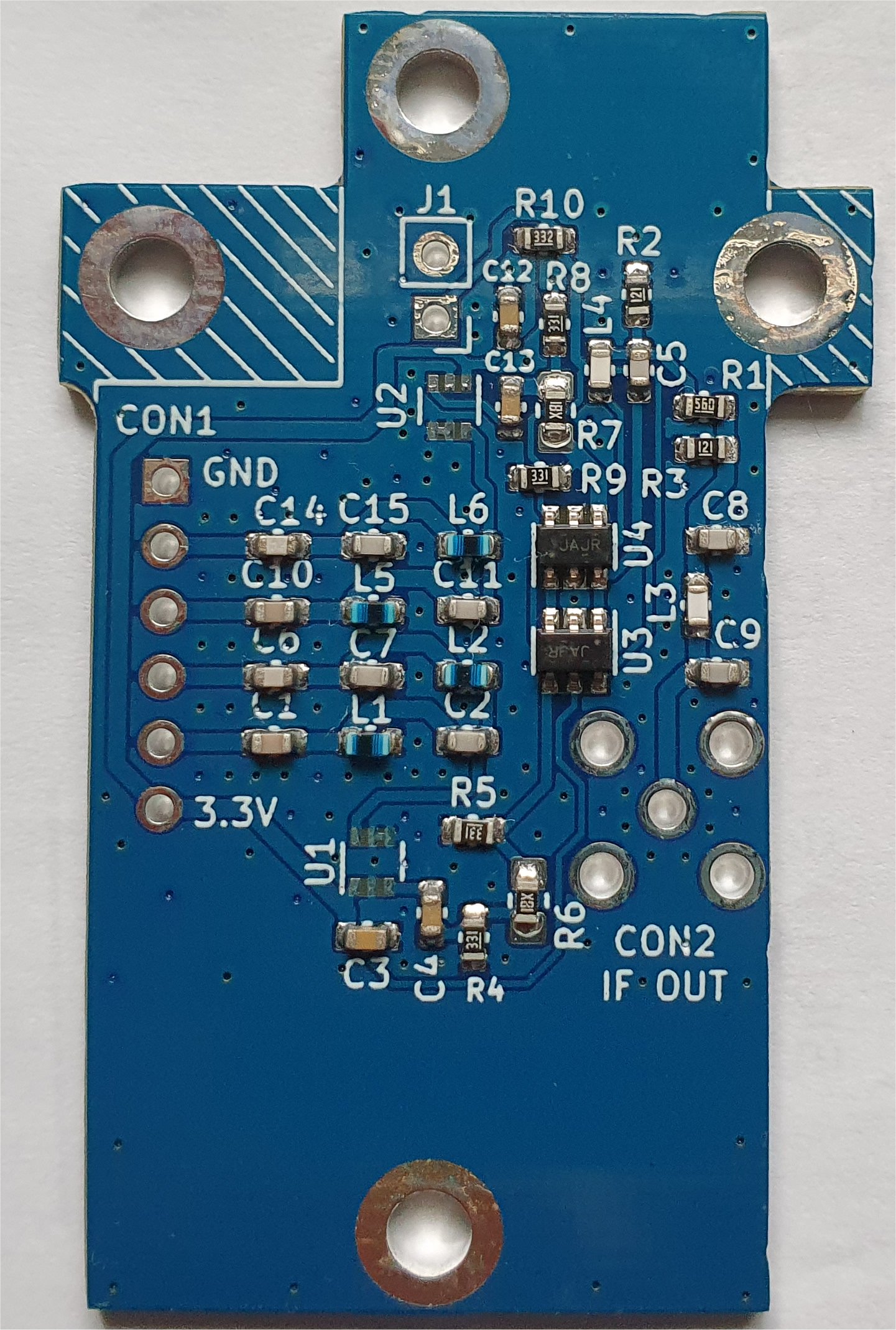
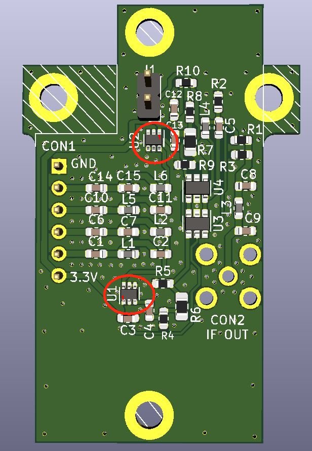
Quadrature boards as supplied and placement of the MMICs.
-Documentation for my display board (jumper settings etc). Updated 9th Feb22 to stress importance of checking connections before fitting the display
-Additional components BOM for the display board.
-Latest Modified Arduino sketchV18-12.2. Update 6/6/21
-detail of Arduino sketch functions.
-Proposed interconnection diagram for my portable system.
-Front panel PLL Schematic (Experimental).
-Versions of Arduino IDE libraries that work! Checked with IDE 1.18.12 .13 and .15 - Unzip to get the 4 zip libraries, then add.
An FAQ is being compiled at the end of this page.
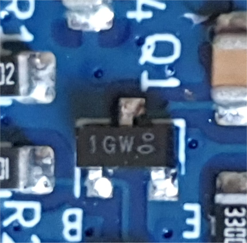
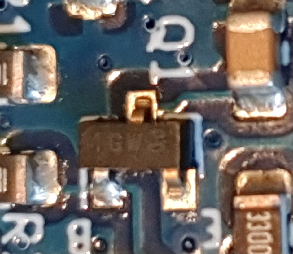
The last batch of boards showed a minor issue with the soldering of Q1. I have seen no problem with earlier batches but its worth a check and possibly reflow the joints.
Two of the pads for Q1 have Vias. This can reduce the quality of the soldered joint by reducing the solder fillet size. I have manually reworked the joints on this batch.
Below are pictures of what the board should look like (earlier batch) and what the last batch was like. A V2.2 board is now designed without Vias in the pads here.
- I will be making these PCBs available to those wishing to implement a display. Please contact me for details of PCB avaiability. eMail address on homepage
Prices, in GB pounds, excluding Post and Packing
Based on 'BULK' Purchase from PCB house. Most of these are no out of stock. The minimum I can order at any time is 5 and the postage overhead is considerable on a small batc
It is expected that the board will be suitable for the new version VK board covering 122 and 134 GHz although the firmwre on the arduino will need updating. More boards may be produced if demand rises.
Prices, will be updated as and when new orders need to be placed
Display PCB SMD populated GBP 8.00 ? (Out of stock Oct 2024)
Display PCB unpopulated GBP 5.00 (Limited stock Oct 2024)
Quadrature boards populated (No MMICs) GBP 8.00 (Out of stock July 2022)
Quadrature boards fully populated inc MMICs GBP 11.00? (Out of stock Oct 2024)
Quadrature boards unpopulated GBP4.00 (Out of stock Oct 24
Display bezel 120 x 95mm GBP 6.00 GBP6.50 (Limited stock Oct 2024)
Display bezel 200 x 95mm GBP 6.50 GBP7.00 (Linited stock Oct 2024)
FAQ
Q Why don't the buttons work?
A Possible construction issues.. Check the link on J5 is set for A5. Check that the 'enter' switch is connected through to pin A5 on the arduino
For some Arduinos, the pin at the end next to A7 & A6 is ground. On the PCB this is the A5 (Enter button) line.
In this case, this board connection must not be made. It will Ground A5.
Only the Enter buton is active initially and a long press or 'double click' is needed.
Q Can I use a different display?
A So long as the display is 160x128 and has the ST7735 Driver, the sketch should work.
It is not guaranteed that my boards will align with the mounting holes for other displays. At least one user has used a different style display sucessfully
but the text was inverted. See the documentation to fix this in the sketch... change tft.setRotation (1); in setup
Q I have programmed different frequencies to the VK3CV board. How do I change the display?
A Lines 144 and 145 in the sketch contain the frequency table. Edit this to suit your new programmed channels.
![]()
Page under construction
Back to the Amateur Radio page
