TVI Filter
Here is a design for a simple television interference filter. It is a 5 pole High Pass filter with a braid break to reduce common mode transmission. Attenuation in the UHF TV band (470 MHz to over 1GHz) is typically between 0.5 and 1.5dB. Attenuation at 144 MHz is typically over 50dB. It can be used to fight TVI from any HF or VHF transmitter system into a UHF TV.
IT WILL NOT STOP HARMONICS FROM THE TRANSMITTER OR ANY INTERFERENCE AT THE TV FREQUENCY.
I have not been able to measure common mode (braid breaking) attenuation. The braid is the most common route for TVI from short-wave transmissions ( HF )
The Board is made of single sided PCB material, and either etched or cut to leave copper as shown. You can omit C4 and R1, and link then out to give a lower ripple in the UHF passband. Typically the loss is 0.3 to 0.8 dB and very flat. You will have no braid break capability, so ferrite rings can be added if needed. With no C4 / R1 a metal enclosure is OK
Layout / board (actual size 35 x 25 mm approx.)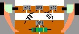 Circuit Diagram
Component values:- C1=C3= 2.2pF C2=3.3pF C4=3.3 or 4.7pF Sub-minature plate ceramic 100V dc working. Low K
The components I use are made by Phillips Components and available from RS components stock no 125-979 for the 2.2pF item. Other types may be used, but they must be small, with short leads and low loss.
R1 is 1MOhm 1/4 W..not critical.
L 1 & 2 are 2 turns 0.5mm Cu wire 5mm OD, approx. 5m long (i.e. wide spaced turns) They are mounted at 90 degrees to each other. To reduce stray coupling.
The coaxial cable is soldered directly to the board, and the lead to the TV should be less than 150mm long, the shorter the better.
The filter MUST NOT be placed in a metal housing, else the braid breaking ability will be lost. I use 25mm white plastic tubular conduit, It is OK to trim the board a bit to make it fit, and you can squeeze the tube to allow the board too sit in tightly.
With the component values as shown the 3dB point will be in the range 300 to 400MHz dependent on construction and coil spacing. The loss in the TV band will be minimal. You can expect 50dB attenuation at 144MHz, sometimes more if the cut off freq is on the high side. The filter effectively stops anything below 250MHz from coming down the coax.. It may ever completely cure the interference problem.. If you are lucky.
If a second filter is required in series with the first, it is likely that the problem is common mode. That is to say the unwanted signal is coming down the outer of the coax. Ferrite rings are a good addition to the braid breaking capability of a system. Wrap a few turns of the coax around a torroid , ensuring that the cable in and out of the ring are kept separate.
