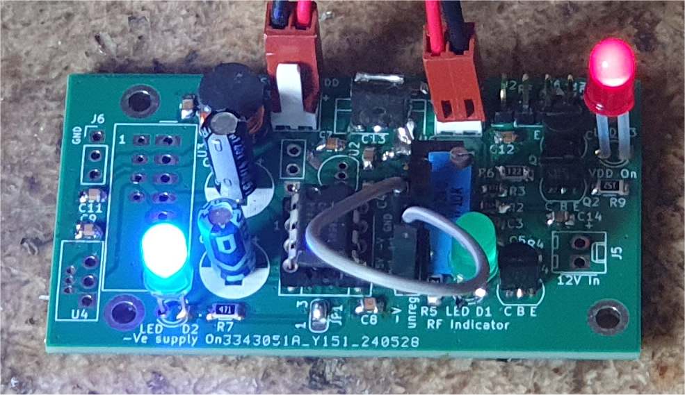
Power Supply management board with integrated -V bias generator
Page under construction!!
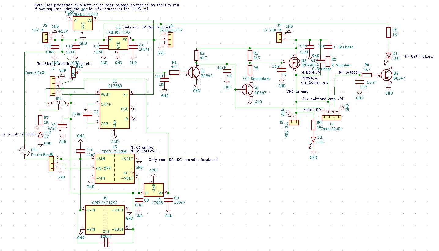
A simple circuit to provide the -V supply for amplifiers or systems requiring a low current -V rail
Many of these systems can suffer catastrophic failure if the -V rail is not present when the +ve supply is applied. The -Ve voltage biases GaAsFets
and loss of this bias results in the device conducting hard, often destroying the device)
This board passes the +Ve supply through a solid state switch. The switch is opened if the -Ve supply is not detected and can also be controlled by an external connection
Thus PTT, over temperature or other fault states can mute the +Ve supply simply by grounding a common pin
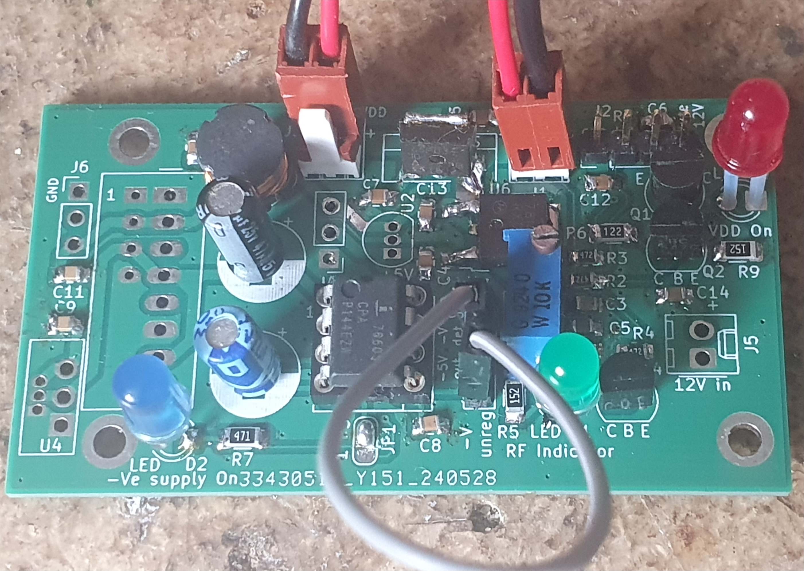
LED indicators of the -V rail and the state of the switched +v output are provided. An addition LED driven be a transistor can be driven by a diode RF detector as often found >/p>
on power amplifiers. This gives a simple visual indication of RF output, ideal for portable operation.
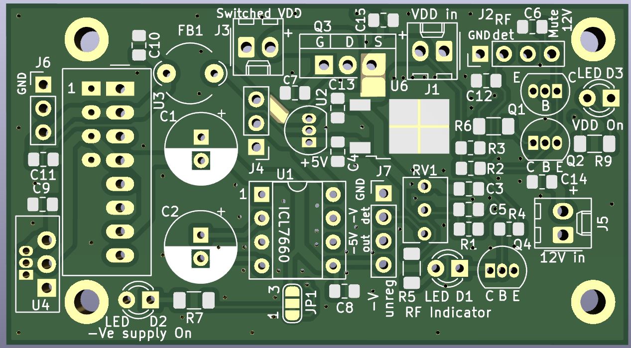
Components on the board are typically 0805 size or larger, through hole components are used in several places to allow design flexibility
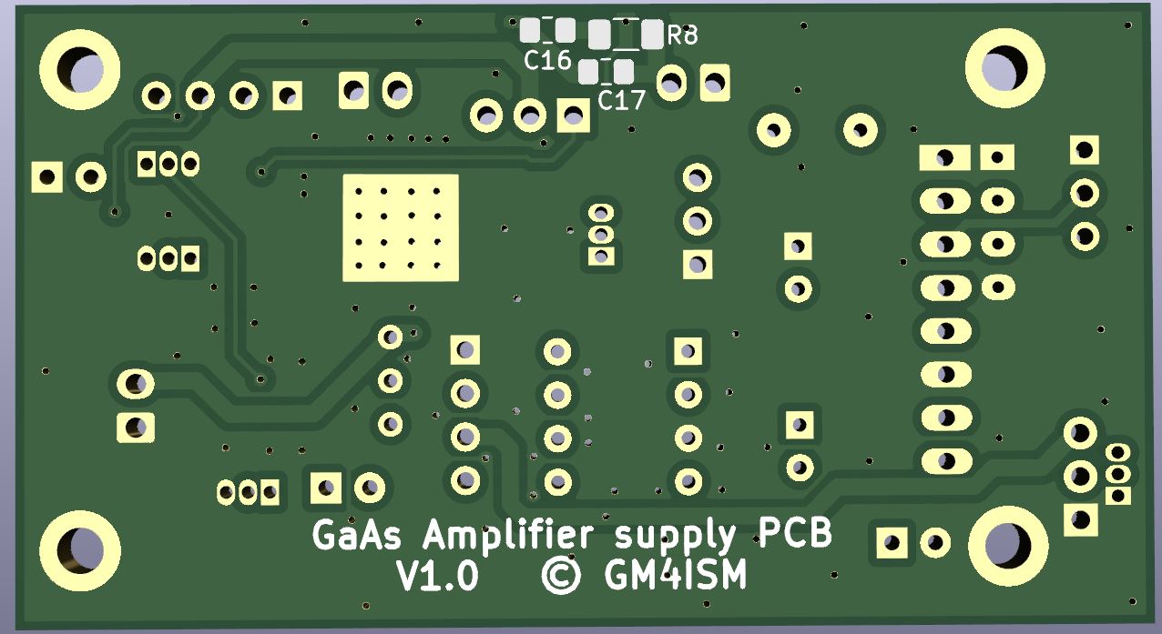
A few V 1.0 prototypes PCBs (unpopulated) have been procured have been tested. They will made available soon, price TBC
With a SUD45P03-15 FET mounted without any heatsink, the board can switch 5A at 15V comfortably (although I don't recommend the KK254 connectors at this current)
Features
12-14V DC in for the -ve Bias generator
Separate DC in for the the Switched Amplifier supply
DC switching up to 5A (depending on switching FET and output connector rating) *See notes
ICL7660 based -Ve voltage generator OR modular DC-DC converters can be fitted.
Variable threshold for -Ve voltage detector. The input for this is on a header and should be connected to the -Ve supply as close to the equipment as possible.
RF detector indicator LED
external PTT Input (inverted). A low impedance signal mutes the PA +Ve supply on RX . Grounding this pin (open collector etc) will mute the +V output. Multiple inputs can be operated in parallel on this pin
The pin is on the base of a bipolar transistor so the input must be taken below 0.5V
-Documentation Setup instructions 1st Draft
NOTE This is a work in progress. Component values etc. may change after evaluation of performance!.
![]()
Page under construction
Back to the Amateur Radio page
