GPS locked frequency standard
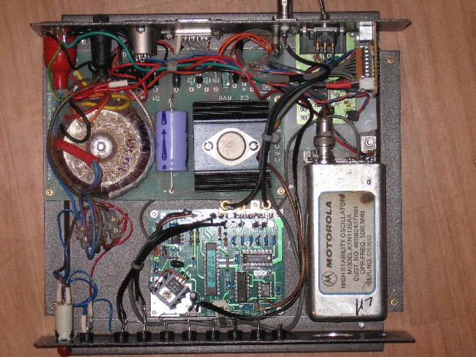
I have built a frequency standard to VE2ZAZ's design using the Trimble Palisade GPS timing receiver.
The 1 PPS signal from the Trimble Palisade is designed for timing applications. The receiver in its default mode, produces 1 PPS as soon as it has 4 satellites locked. After a while the receiver uses an average of the received position information and 'locks' to this position. This enables it to more accurately determine the timing of the 1 PPS signal, reducing the jitter (short term instability) of the 1PPS. A typical automotive application GPS engine, such as the Motorola Oncore or the Jupiter TU30, has jitter up to 500nS. The Trimble Palisade can manage 50nS. This means the time constants on the frequency locked loop could be relaxed without compromising short term stability.
Full details can be found on Bert's webpage
This required only a little additional interfacing, as the Palisade uses RS422 diferential serial comms. Details of the interface (using a 75ALS175 and a 75ALS174) is below.
The manual for the Trimble Palisade can be found here ( pdf zipped, 1.6Mb). Connection data and details of the connector are in the manual. for quick reference the connector is manufactured by Deutsch and is MMP series, #26C-2212S1 (requires moulded backshell, part no. 6810-204-2001 and sockets, part no. 6862-201-22278) Info from Richard AA6RS
Early software for talking to the Trimble Palisade (TSIPmon32) is here. A later version is downloadable from Trimble here.
Beware, I tried to force the receiver to talk NMEA, and it locked up. I have yet to discover why, or get the unit working again! Further investigation has shown that the unit has been set to 7 bit serial data format somehow. This is not good. It needs 8bit commands!
Andy G4JNT has written a simple protocol converter that runs on a 16F628 PIC and changes the Trimble data to NMEA. Only the timestamp is reproduced in the $GPRMC string at present and the data stream must come from the Palisade port A (pins 8 and 10), not the B port as used to display information using the Trimble software. The sense of the TTL logic levels into and out of the PIC seem to be inverted. The logic levels do not need inverting from the PIC to the RDDS keyed synthesizer used in a number of amateur microwave beacons.
The source code for this can be downloaded from Andy's site here
I have a number of the Trimble Palisade receivers for sale, though I have no spare connectors for them.
Email me for details (see home page)
Positioning a GPS antenna
Obviously the ideal location for the antenna is outside with a clear view of the sky down to horizon. Given ideal conditions 8-12 satellites will often be in view. Once a good 3d lock is obtained (requiring 4 satellites) and the GPS receiver has gone to manual mode (it assumes a fixed location) after about 1/2 Hour, the 1PPS will operate satisfactorily using 3 birds (in fact only one is needed). This means that the antenna position does not need to be perfect for a useable system.
Not often noted, the GPS satellites are in an inclined polar orbit.... 55 deg inclined to be precise. This means that in the UK there is a big hole in the sky to the North that the satellites never cross. See the image capturing the recorded tracks of the birds over a couple of days.
A moderate view of just the northern sky from the UK may not work too well!! (I found out the hard way) pointing the antenna out of a ground floor northerly window netted only 1 bird at a time for hours on end...
Page under construction
![]()
Back to the Amateur Radio page
