 Fig 1
Fig 1
28V at 50 Amps
Modification details
Disclaimer
This power supply contains dangerous voltages. Modification of these units is at your own risk. Modifications have been tested but no liability can be accepted for any damages resulting from modification, use or misuse of the unit. These notes are for guidance only and are not an approved by the manufacturer. Use of a high current PSU must involve an understanding of the good electrical practices necessary for safe operation.
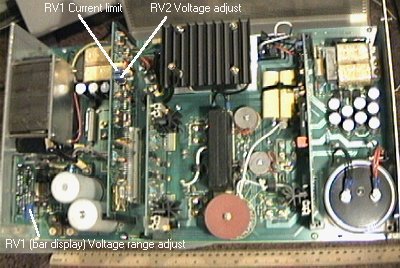
Remove the side cover of the power supply. Internal view below: -
Fig 1
Note the location of the bar graph display board (PCB 3077-2) and the main control board (PCB 3036-3)
On the control board (fig 2) locate RV2 (10K)
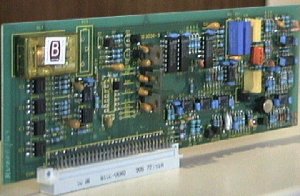 Fig 2 Fig 2 |
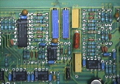 Fig 3 Fig 3 |
RV2 will allow the output voltage to be set within the nominal range of 21 32 V
To provide output voltages lower than this, replace RV1 with a higher value.
50 K will change the range to about 11.5V 32V With RV2 open CCT the
minimum voltage is about 9V. 10 V operation is possible by changing R70
(near 2 pots and C15) from 47K to 470K. The current limit is unaffected
by this modification.
To alter the Voltage metering, use the 10 K pot that was taken from the control board.
Use this to replace RV1 on the back of the Bar display board (500 ohms), and replace R6 with a wire link (or short it out) see Fig 4
This allows the Voltage bar graph to be set to a suitable 10V range (1V per segment)
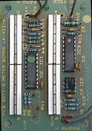 Fig 4 Fig 4 |
 |
A crowbar circuit is reccomended, see above right.
Note that the Zener voltage required depends slightly on the type of SCR
To test the crowbar, simply use RV2 to increase the PSU output voltage until a trip occurs. Note the actual trip voltage!
The overcurrent protection should work, and the fuse should not blow.
A new scale for the voltage bar graph is below. Affix with clear plastic adhesive strip, e.g. Fablon, a piece of Modern Dymo labeller or even Sellotape.
![]()
Known faults
If these power supplies are not used for a long time, they have a tendency to fail on switch on. All the units I had stored failed this way. All but one have been repared by replacing all the tantalum capacitors on the control board shown in fig 2 above. One had additional damage to a large wirewould resistor at the back of the unit on the main board.
Look out for an overheated resistor on the voltage current indicator PCB.. replace the 1/4W resistor with a 1/2W version if required.
Note that RF filtering of the output is recommended for amateur radio use!
