
PCB to enable the RP2040 Zero to be interfaced with various PLL evaluation boards
Designed for compatibility with G4EML 's firmware on GitHub
Page under construction!!
The 1st batch of V1.1 boards has arrived from JLCPCB. It has now been tested for the 2 main supported boards with GPS and LED lock driver using the components that will be supplied with this batch
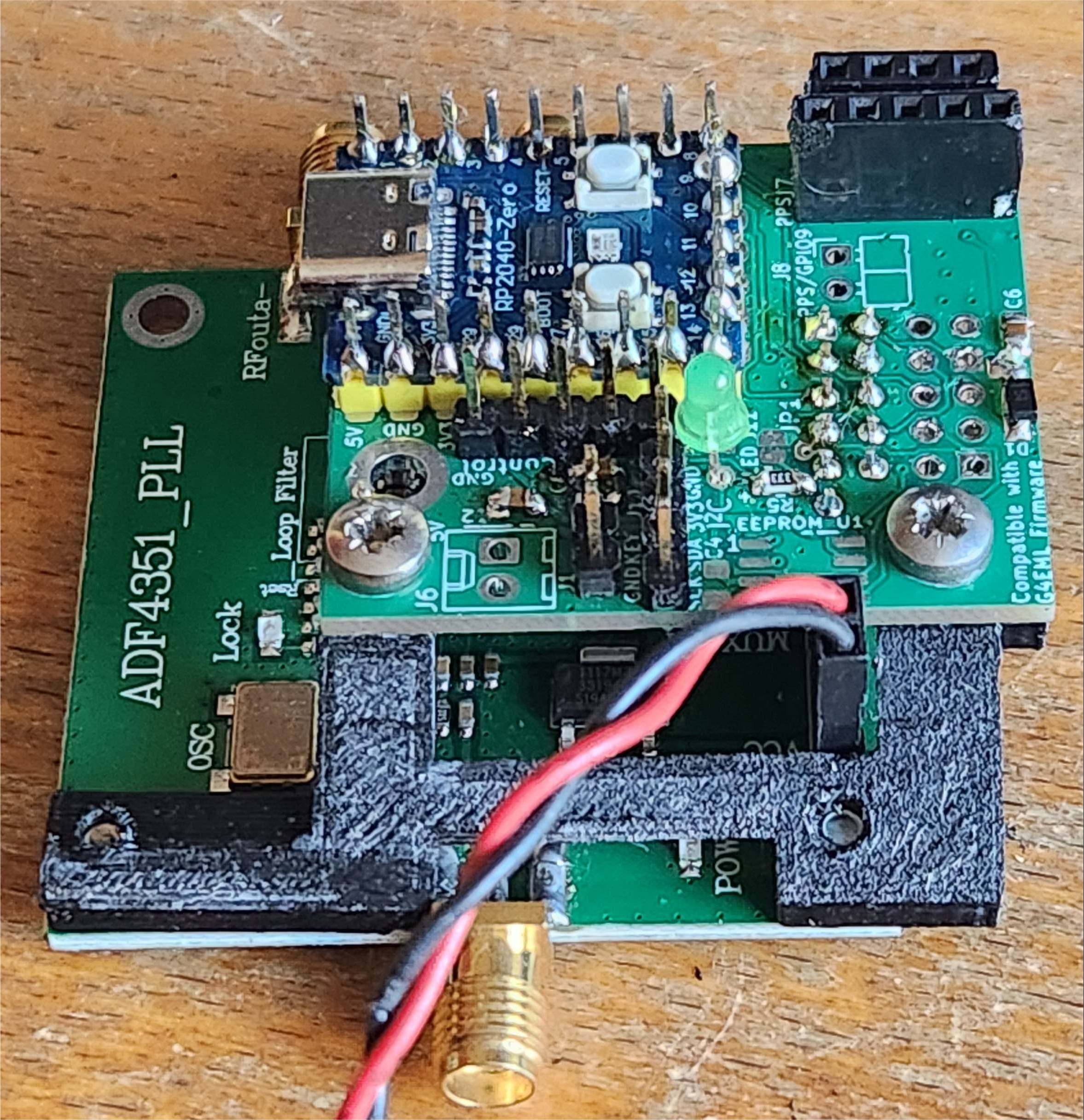
Tested OK with the MAX2870 and ADF4351 boards that share header config.
GPS headers Tested OK with 2 types of NEO-6M boards that I have
Lock Detect driver Tested OK with the MAX2870 and ADF4351.
.Onboard 3.3V regilator Tested OK with 130mA output. For thermal reasons this is the max reccomended as implemented. This can run the SV1AFN PLL board.
A single cut to a track and adding a series 500mA rated diode to the input of the 3.3V reg enables output of 240mA Max. This mod will is incorporated in the production V1.1 board.
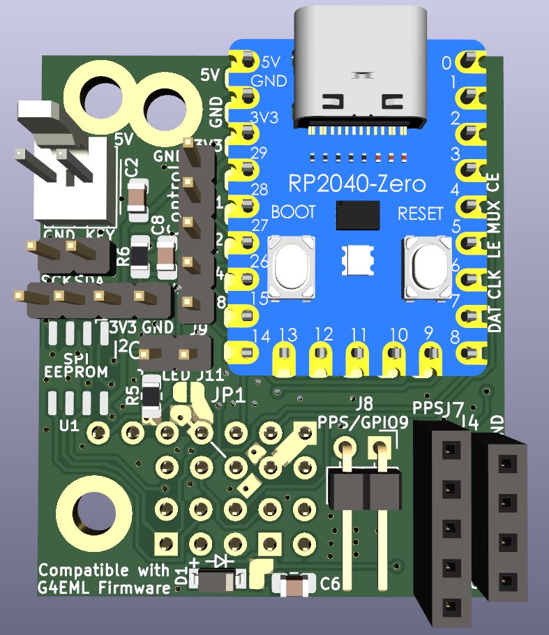
The PCB marshals SPI etc from the RP2040 Zero and is designed to plug directly onto several PLL evaluation board headers
Supports channel switching, Morse Key input, external GPS engine, optional true EEPROM for the RP2040
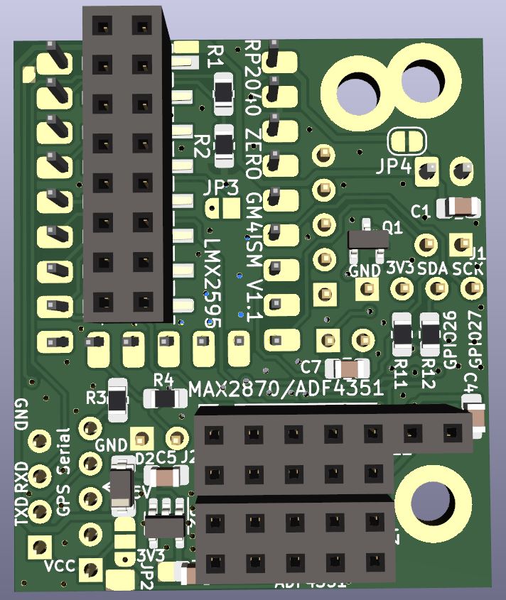
Supports several varieties of ADF4351 Evaluation board (including SV1AFN), MAX2870 and MAX2575 boards
Offers plugin support for some ADF5355 boards (Firmware not yet available)
Pads are provided for optional supply line decoupling, 3.3V rail segregation diode, lock detect indication (where presented) and an onboard 3.3V regulator if needed.
Additional optional components are 0805 size or bigger for ease of construction
-Video Video of ADF4351 test on 2m running JT4G
Documentation Provisional Setup instructions Issue 3 covering V1.0 and V1.1 boards
Mechanical support for type4 PLL board STL File for 3D printer


V1.1, the first production run of 100 is here and the additional components for the short kits have just arrived. All of this run are already allocated.
Final checks and processing of confirmed orders has started but due to family commitments, I am away again until until early June so there may be a small delay in getting these sent..
Subject to sufficient demand another batch can be ordered.
The V1.1 board schematic is little changed in most aspects. Layout has been ennhanced to allow easier use with yet more variants of the ADF4351 PLLs
The SV1AFN ADF4351 PLL board needs 3.3V fed to it and the onboard LDO regulator, which can be used for this, now has provision for an optional extra voltage dropper to improve its operation at high loads.
the choice of an ultra low noise regulator for this application is important.
Please also note that due to an error, the header for the SV1AFN PLL is rotated 180 degrees. The board works fine (now I have got hold of the PLL board and tested it) but the hat does not sit above the PLL as intended
I have had just over 100 expressions of interest but not all have yet confirmed and placed an order. Should there be sufficient additional interest I can have more made
The cost of bare board will be £1.00 each
A short kit with the board, an SMD Schottky diode, 2 off 100nF 0805 caps and a 2x5 header for the PLL connection will be £1.50 each
UK postage, 10 bare boards or less £1.50... Boards with additional components £2.00. EU postage £3.30 to £3.75 depending on weight
Postage otside Europe can be calculated on request.
Details of the V1.1 board below.
NOTE This is a work in progress. Component values etc. may change after evaluation of performance!.
![]()
Page under construction
Back to the Amateur Radio page
