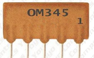
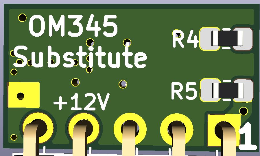
Philips OM345 Substitute for the MI2955
Page under construction!!
Winner of the Scottish Microwave Round Table (GMRT) construction contest 2023.
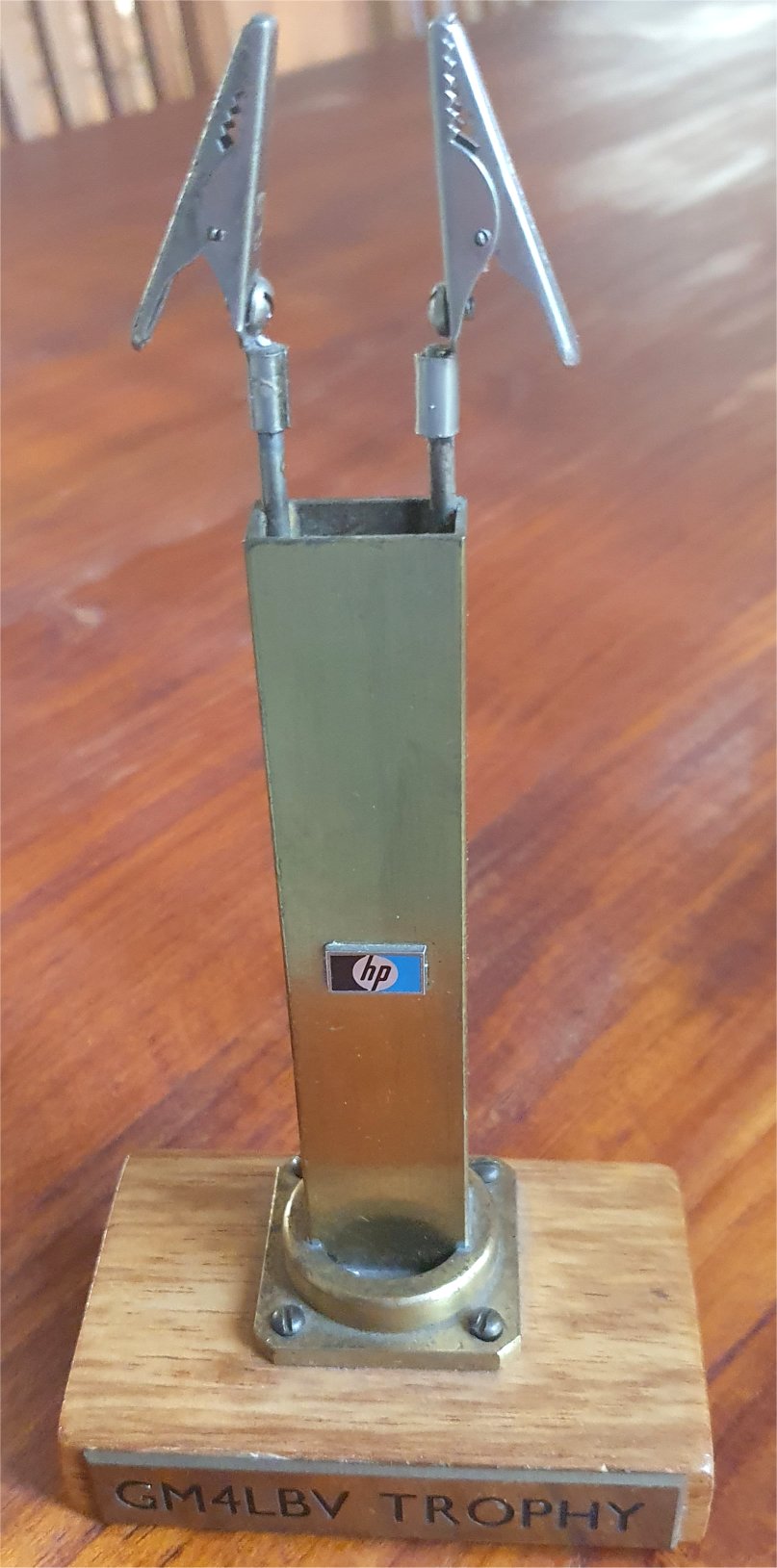
The infamous 'Wave-guide to crocodile clip adaptor'
The OM345 is a hybrid IC RF amplifier. It has been obsolete for many years and is hard to source.
It is used in some of Marconi Instruments test equipment, notably the MI2955 RF test set .
Unfortunatley this eldery device has a tendency to fail, rendering the test equipment inoperative.
In many cases the failure mode has been traced to one of the resistors in the device. There is a work arround / fix
that involves fitting a 4K7 resistor externally between Pins 1 and 5, or scraping off the outer coating and fitting a new surface mount resistor.
Details of these repairs can be found easily on the web. For simplicity this really is a good fix!
The other alternative is to fit a home made substitute device. Several versions have been made in the past, with transistors or more often MMIC RF amplifier chips
At the time of writing all sources of the substitutes have pretty much dried up.
As far as I can see, none are a perfect match for all the original OM345 parameters but it seems all work in the MI2955, which is not too fussy.
Now I have a fault on my MI2955, I started to look for these chips, just in case i need a couple.
There are a very limited number in circulation so I decided to investigate having some made.
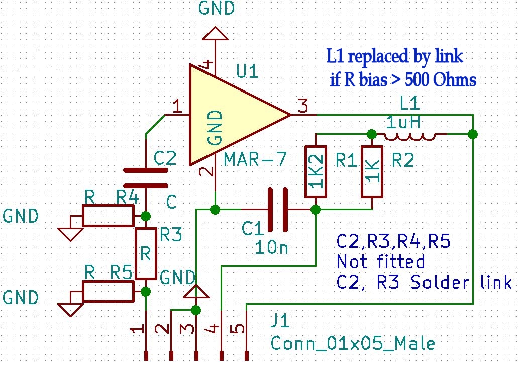
The circuit is very simple. It took very little time to produce a design in Kicad.
Having the PCBs made (and partially populated with the small SMD components) is quite cost effective.
The aim is to produce a plug and play substitute for the OM345. This is harder than it may seem, many MMICS have the wrong gain and dont match the gain flatness of the OM345.
Another consideration is the bias current. The OM345 takes only 12mA at 12V, most otherwise suitable MMICs take more.
There is documented evidence that the MI2955 can support MAR7 MMICs with 22mA current and they are close enough in gain for this instrument.
The MAR7 has reasonable gain flatness and perhaps a little too much gain. Decreasing its bias current a little is likley to acheive a better fit for the OM345 parameters.
It will still take a little more current but I expect most other parameters will be close to original.
I suspect that most circuits that employ the OM345 will have sufficient headroom on the 12V rail to cope with a few more mA. A compromise here seems the best course for more universal use.
It must be emphasised that there is no guarantee that a MAR7 based substitute device will sucessfully replace an OM345 in all circumstrances but it seems that it suitable for the MI2955.
The PCBs have been designed so that other MMICs could be used. An on-board attenuator on the input (not fitted as standard) means that devices with higher intrinsic gain can be tried.
The device noise figure will be degraded but modern devices often have much lower intrinsic noise figures than the OM345
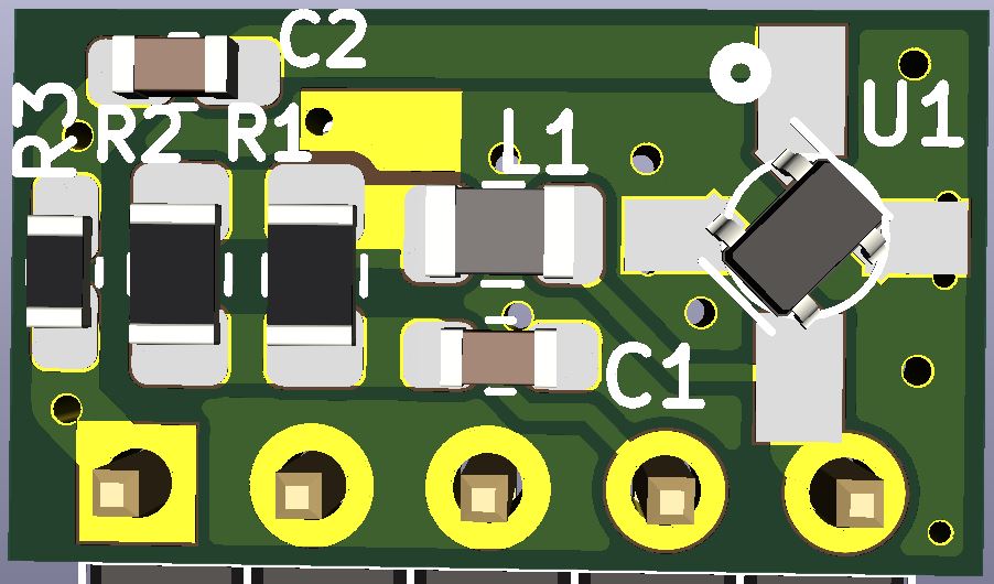
The surface mount inductor as supplied on pre-populated boards from the PCB house, is rated at 50mA , suitable for many devices.
Please note the 3d Image below shows a SOT-343 MMIC, The MAR 7+ is the WW107 package. The board is designed for both and also supports SOT363 for the MGA-81563.
Subject to availabliliy of the MMICs the expected costs of these boards, if produced in moderate quantities, will be announced if demand hits minimum levels:-
Bare PCB GBP 1.00
PCB with passive SMD components fitted (suited to MGA-81563) GBP TBC
Fully populated as above (MGA-81563 and pins manually assembled, L replaced by link) ready to use OM345 substitute GBP TBC
P&P not included, TBA.
NOTE This is a work in progress. Component values etc. may change after evaluation of performance!.
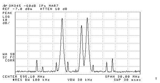
Linearity and output power capability was a potential issue, especially with the restricted device current needed to get faltter, lower gain preformance. The OM345 datasheet does not specify P1dB as modern devices do.
Output power is specifiied as 99dBuV RMS (into 75 ohms) with -60dB Ips, 3 tones as per DIN 45004 para 6.3, referenced in this Philips app note
>This emulates an analogue TV composite signal with sound subcarrier.
I now have access to the test equipment for doing this measurement (BBC Engineering Designs Dept 3/4 tone tester, GE4P/17) and have evaluated the design against this spec..
The measured level for -60dB IPs is -6.2dBm into 50 Ohms (Quality power meter), not the spectrum analyser. This is approximatly 101dBuV, exceeding the OM345 spec.
To get a more accurate measurement the power meter (which is not a calorific type), needs to have the error that comes from the multi tone measurement accounted for.
This error will work in our favor. The power meter and head were designed to accomodate 'multi tone' COFDM signals, so I knew the answer would lie between the calorific value and the 3 tone peak value.
Using the power meter to measure the single tone 0dB level and then setting the 3 tone levels the power meter would still read 0dB if it measured the true peak power
If it read the calorific value it would read 0.3831 x the 0dB level (-4.17dB) It actually read -3.25dB
Correcting for this, the OM345 substitute was actually producing a nominal -3dBm peak for the -60dB IPs. This is 104dBuV
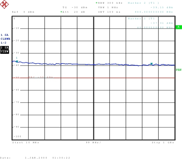
Test results so far for MAR 7+ Based unit biased at 13.5mA. (Note a bias resistor value of 600 Ohm should give 18mA, but it doesn't with this batch of devices)
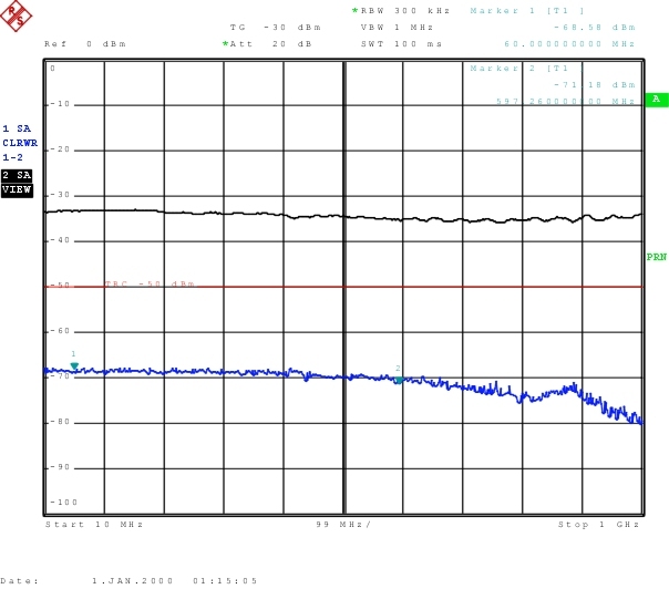
Reverse Isolation.
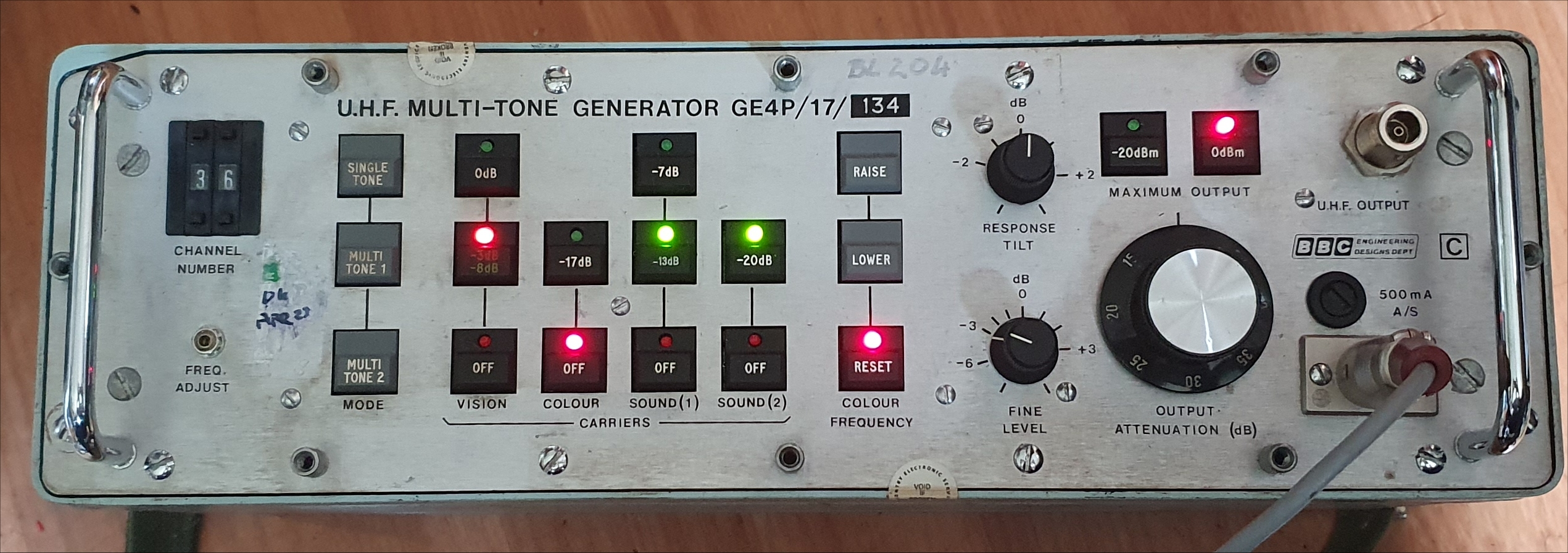
Test generator for DIN 45004 intermodulation tests.
I have identified another device (MGA-81563) that gives better gain flatness (and a little more gain) at the expense of a significantly higher bias current (42mA).
The excess gain could be removed with a 1 to 2 dB attenuator on the input (my PCB can accomodate this). The intrinsic device noise figure is degraded of course
but since the MGA-81563 has a noise figure of about 3dB, this maintains the substitute device nf as per the spec for the OM345
I throttled back the bias a little on this device to 37.5mA, gain droped about 1dB to a reasonable level.
The measured (and peak corrected) level for -60dB IPs is -0.25dBm into 50 Ohms. This is approximatly 107dBuV, again exceeding the OM345 spec.
Further tests on this device are needed but the latest version of PCB will be designed to accomodate them.
OM345 Substitute using MGA-81563
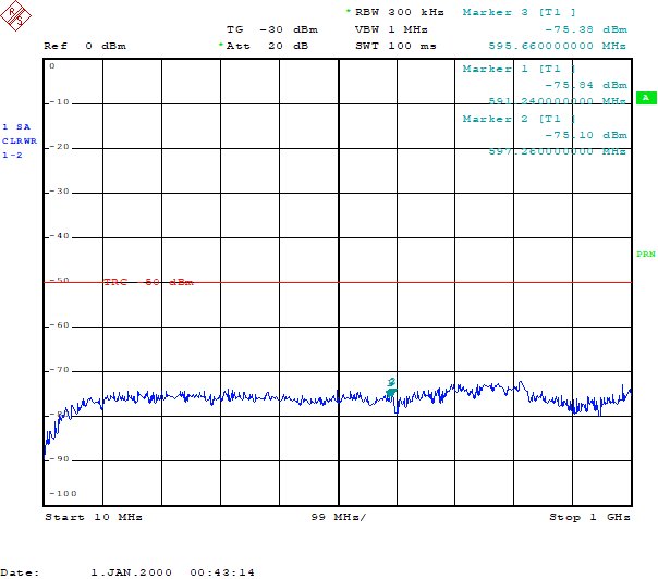
Reverse Isolation.
